
MFC - Quick Guide
MFC - Overview
The Microsoft Foundation Class (MFC) library provides a set of functions, constants, data types, and classes to simplify creating applications for the Microsoft Windows operating systems. In this tutorial, you will learn all about how to start and create windows based applications using MFC.
Prerequisites
We have assumed that you know the following −
- A little about programming for Windows.
- The basics of programming in C++.
- Understand the fundamentals of object-oriented programming.
What is MFC?
The Microsoft Foundation Class Library (MFC) is an "application framework" for programming in Microsoft Windows. MFC provides much of the code, which are required for the following −
- Managing Windows.
- Menus and dialog boxes.
- Performing basic input/output.
- Storing collections of data objects, etc.
You can easily extend or override the basic functionality the MFC framework in you C++ applications by adding your application-specific code into MFC framework.
MFC Framework
The MFC framework provides a set of reusable classes designed to simplify Windows programming.
MFC provides classes for many basic objects, such as strings, files, and collections that are used in everyday programming.
It also provides classes for common Windows APIs and data structures, such as windows, controls, and device contexts.
The framework also provides a solid foundation for more advanced features, such as ActiveX and document view processing.
In addition, MFC provides an application framework, including the classes that make up the application architecture hierarchy.
Why MFC?
The MFC framework is a powerful approach that lets you build upon the work of expert programmers for Windows. MFC framework has the following advantages.
It shortens development time.
It makes code more portable.
It also provides tremendous support without reducing programming freedom and flexibility.
It gives easy access to "hard to program" user-interface elements and technologies.
MFC simplifies database programming through Data Access Objects (DAO) and Open Database Connectivity (ODBC), and network programming through Windows Sockets.
MFC - Environment Setup
Microsoft Visual C++ is a programming environment used to create applications for the Microsoft Windows operating systems. To use MFC framework in your C++ application, you must have installed either Microsoft Visual C++ or Microsoft Visual Studio. Microsoft Visual Studio also contains the Microsoft Visual C++ environment.
Microsoft provides a free version of visual studio which also contains SQL Server and it can be downloaded from https://www.visualstudio.com/en-us/downloads/downloadvisual- studio-vs.aspx.
Following are the installation steps.
Step 1 − Once Visual Studio is downloaded, run the installer. The following dialog box will be displayed.
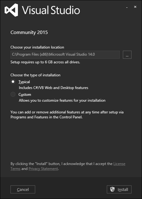
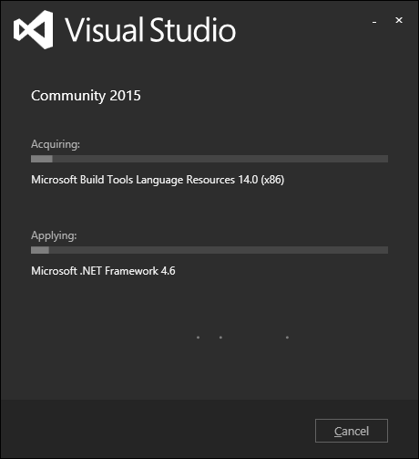
Step 2 − Click Install to start the installation process.
Step 3 − Once Visual Studio is installed successfully, you will see the following dialog box.
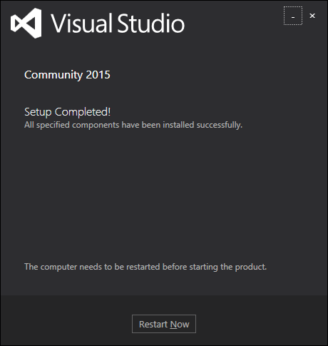
Step 4 − Close this dialog box and restart your computer if required.
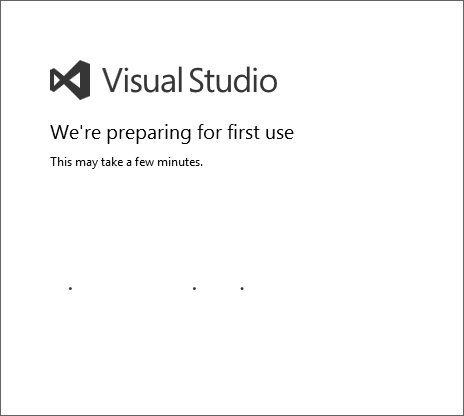
Step 5 − Open Visual studio from the Start menu, which will open the following dialog box. It will take some time for preparation, while starting for the first time.
Step 6 − Next, you will see the main window of Visual Studio.
Step 7 − You are now ready to start your application.
MFC - VC++ Projects
In this chapter, we will be covering the different types of VC++ projects. Visual Studio includes several kinds of Visual C++ project templates. These templates help to create the basic program structure, menus, toolbars, icons, references, and include statements that are appropriate for the kind of project you want to create. Following are some of the salient features of the templates.
It provides wizards for many of these project templates and helps you customize your projects as you create them.
Once the project is created, you can build and run the application.
You don't have to use a template to create a project, but in most cases it's more efficient to use project templates.
It's easier to modify the provided project files and structure than it is to create them from scratch.
In MFC, you can use the following project templates.
| Sr.No. | Project Template & Description |
|---|---|
| 1 | MFC Application An MFC application is an executable application for Windows that is based on the Microsoft Foundation Class (MFC) Library. The easiest way to create an MFC application is to use the MFC Application Wizard. |
| 2 | MFC ActiveX Control ActiveX control programs are modular programs designed to give a specific type of functionality to a parent application. For example, you can create a control such as a button for use in a dialog, or toolbar or on a Web page. |
| 3 | MFC DLL An MFC DLL is a binary file that acts as a shared library of functions that can be used simultaneously by multiple applications. The easiest way to create an MFC DLL project is to use the MFC DLL Wizard. |
Following are some General templates which can also be used to create MFC application −
| Sr.No. | Project Template & Description |
|---|---|
| 1 | Empty Project Projects are the logical containers for everything that's needed to build your application. You can then add more new or existing projects to the solution if necessary. |
| 2 | Custom Wizard The Visual C++ Custom Wizard is the tool to use when you need to create a new custom wizard. The easiest way to create a custom wizard is to use the Custom Wizard. |
MFC - Getting Started
In this chapter, we will look at a working MFC example. To create an MFC application, you can use wizards to customize your projects. You can also create an application from scratch.
Create Project Using Project Templates
Following are the steps to create a project using project templates available in Visual Studio.
Step 1 − Open the Visual studio and click on the File → New → Project menu option.
Step 2 − You can now see that the New Project dialog box is open.
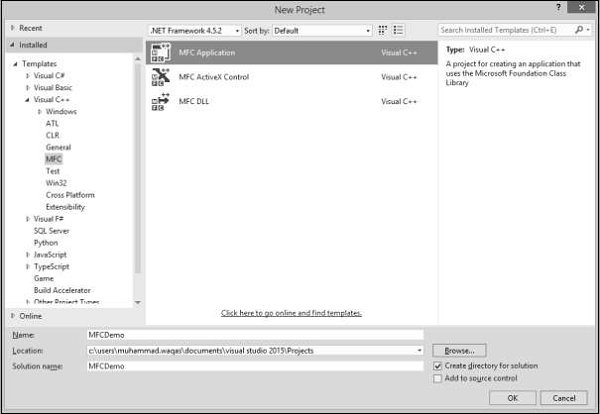
Step 3 − From the left pane, select Templates → Visual C++ → MFC
Step 4 − In the middle pane, select MFC Application.
Step 5 − Enter the project name ‘MFCDemo’ in the Name field and click OK to continue. You will see the following dialog.
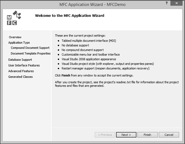
Step 6 − Click Next.
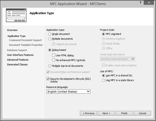
Step 7 − Select the options which are shown in the dialog box given above and click Next.
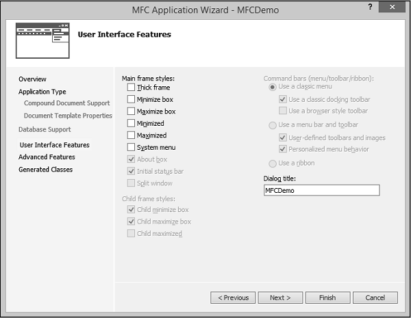
Step 8 − Uncheck all options and click Finish button.
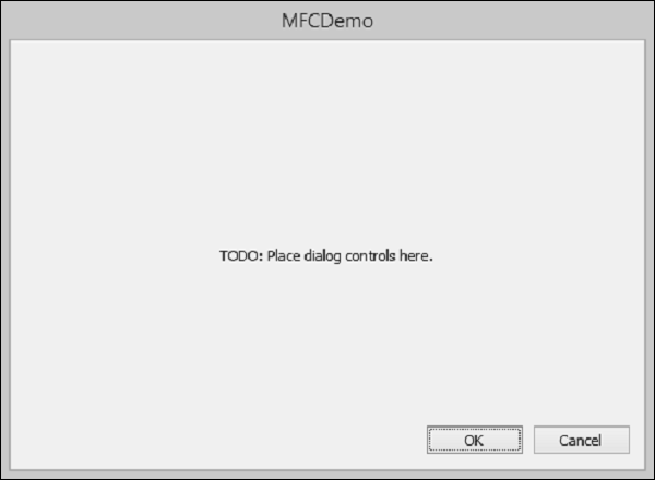
You can now see that the MFC wizard creates this Dialog Box and the project files by default.

Step 9 − Run this application, you will see the following output.
Create Project from Scratch
You can also create an MFC application from scratch. To create an MFC application, you need to follow the following Steps.
Step 1 − Open the Visual studio and click on the File → New → Project menu option.
Step 2 − You can now see the New Project dialog box.
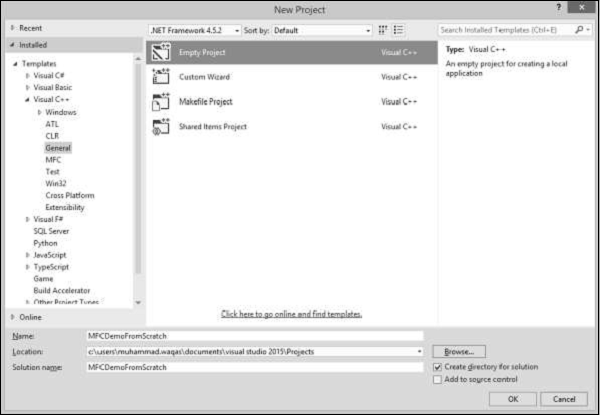
Step 3 − From the left pane, select Templates → Visual C++ → General.
Step 4 − In the middle pane, select Empty
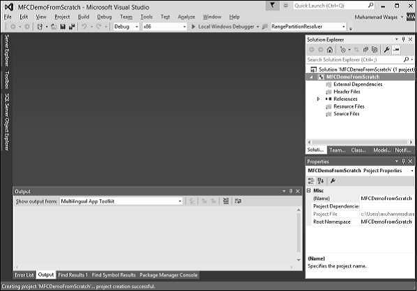
Step 5 − Enter project name ‘MFCDemoFromScratch’ in the Name field and click OK to continue. You will see that an empty project is created.
Step 6 − To make it an MFC project, right-click on the project and select Properties.
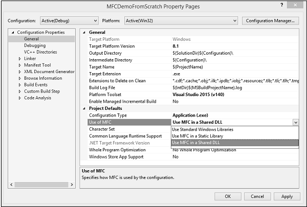
Step 7 − In the left section, click Configuration Properties → General.
Step 8 − Select the Use MFC in Shared DLL option in Project Defaults section and click OK.
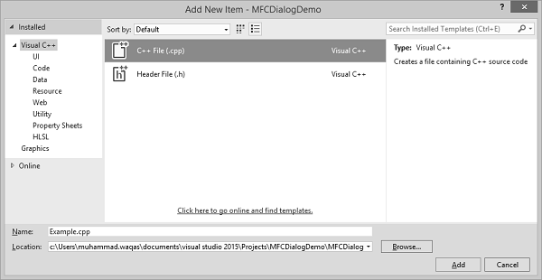
Step 9 − As it is an empty project now; we need to add a C++ file. So, right-click on the project and select Add → New Item…
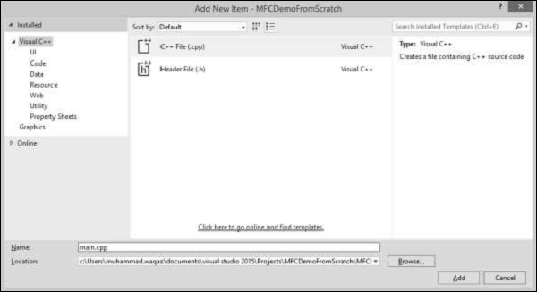
Step 10 − Select C++ File (.cpp) in the middle pane and enter file name in the Name field and click Add button.
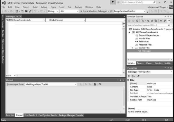
Step 11 − You can now see the main.cpp file added under the Source Files folder.
Step 12 − Let us add the following code in this file.
#include <iostream>
using namespace std;

void main() {
   cout << "***************************************\n";
   cout << "MFC Application Tutorial";
   cout << "\n***************************************";
   getchar();
}
Step 13 − When you run this application, you will see the following output on console.
***************************************
MFC Application Tutorial
***************************************
MFC - Windows Fundamentals
In this chapter, we will be covering the fundamentals of Windows. To create a program, also called an application, you derive a class from the MFC's CWinApp. CWinApp stands for Class for a Windows Application.
Let us look into a simple example by creating a new Win32 project.
Step 1 − Open the Visual studio and click on the File → New → Project menu option.
Step 2 − You can now see the New Project dialog box.
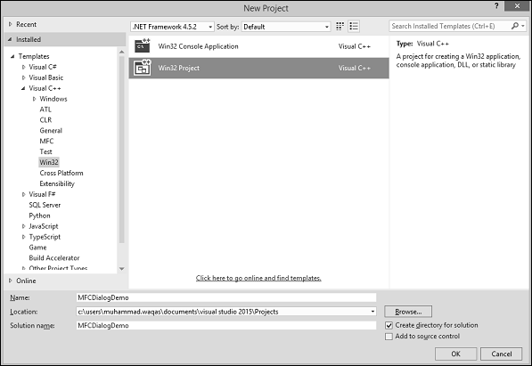
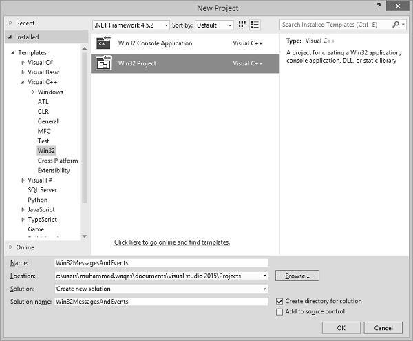
Step 3 − From the left pane, select Templates → Visual C++ → Win32.
Step 4 − In the middle pane, select Win32 Project.
Step 5 − Enter the project name ‘MFCWindowDemo’ in the Name field and click OK to continue. You will see the following dialog box.
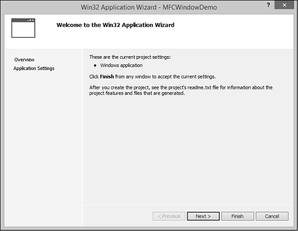
Step 6 − Click Next.
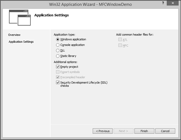
Step 7 − Select the options as shown in the dialog box given above and click Finish.
Step 8 − An empty project is created.
Step 9 − To make it an MFC project, right-click on the project and select Properties.
Step 10 − In the left section, click Configuration Properties → General.
Step 11 − Select the Use MFC in Shared DLL option in Project Defaults section and click OK.
Step 12 − Add a new source file.
Step 13 − Right-click on your Project and select Add → New Item...
Step 14 − In the Templates section, click C++ File (.cpp).
Step 15 − Set the Name as Example and click Add.
Window Creation
Any application has two main sections −
- Class
- Frame or Window
Let us create a window using the following steps −
Step 1 − To create an application, we need to derive a class from the MFC's CWinApp.
#include
class CExample : public CWinApp {
   BOOL InitInstance() {
      return TRUE;
   }
};
Step 2 − We also need a frame/window to show the content of our application.
Step 3 − For this, we need to add another class and derive it from the MFC's CFrameWnd class and implement its constructor and a call the Create() method, which will create a frame/window as shown in the following code.
class CMyFrame : public CFrameWnd {
   public:
      CMyFrame() {
         Create(NULL, _T("MFC Application Tutorial"));
      }
};
Step 4 − As you can see that Create() method needs two parameters, the name of the class, which should be passed as NULL, and the name of the window, which is the string that will be shown on the title bar.
Main Window
After creating a window, to let the application use it, you can use a pointer to show the class used to create the window. In this case, the pointer would be CFrameWnd. To use the frame window, assign its pointer to the CWinThread::m_pMainWnd member variable. This is done in the InitInstance() implementation of your application.
Step 1 − Here is the implementation of InitInstance() in CExample class.
class CExample : public CWinApp {
   BOOL InitInstance() {
      CMyFrame *Frame = new CMyFrame();  m_pMainWnd = Frame;

      Frame->ShowWindow(SW_NORMAL);
      Frame->UpdateWindow();

      return TRUE;
   }
};
Step 2 − Following is the complete implementation of Example.cpp file.
#include <afxwin.h>

class CMyFrame : public CFrameWnd {
   public:
      CMyFrame() {
         Create(NULL, _T("MFC Application Tutorial"));
      }
};

class CExample : public CWinApp {
   BOOL InitInstance() {
      CMyFrame *Frame = new CMyFrame();
      m_pMainWnd = Frame;

      Frame->ShowWindow(SW_NORMAL);
      Frame->UpdateWindow();

      return TRUE;
   }
};

CExample theApp;
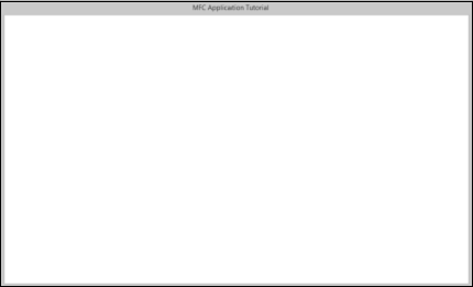
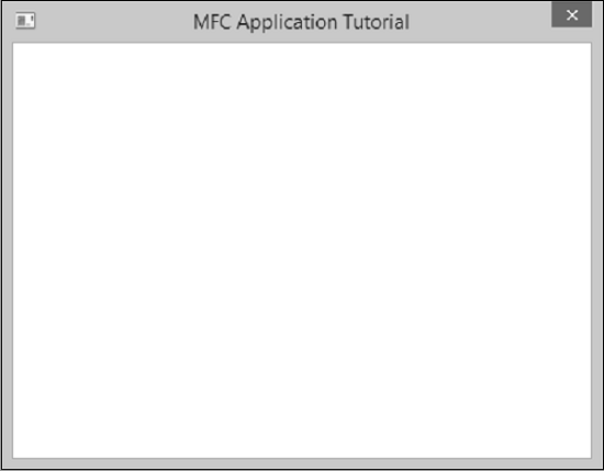
Step 3 − When we run the above application, the following window is created.
Windows Styles
Windows styles are characteristics that control features such as window appearance, borders, minimized or maximized state, or other resizing states, etc.
| Sr.No. | Style & Description |
|---|---|
| 1 | WS_BORDER Creates a window that has a border. |
| 2 | WS_CAPTION Creates a window that has a title bar (implies the WS_BORDER style). Cannot be used with the WS_DLGFRAME style. |
| 3 | WS_CHILD Creates a child window. Cannot be used with the WS_POPUP style. |
| 4 | WS_CHILDWINDOW Same as the WS_CHILD style. |
| 5 | WS_CLIPCHILDREN Excludes the area occupied by child windows when you draw within the parent window. Used when you create the parent window. |
| 6 | WS_CLIPSIBLINGS Clips child windows relative to each other; that is, when a particular child window receives a paint message, the WS_CLIPSIBLINGS style clips all other overlapped child windows out of the region of the child window to be updated. (If WS_CLIPSIBLINGS is not given and child windows overlap, when you draw within the client area of a child window, it is possible to draw within the client area of a neighboring child window.) For use with the WS_CHILD style only. |
| 7 | WS_DISABLED Creates a window that is initially disabled. |
| 8 | WS_DLGFRAME Creates a window with a double border but no title. |
| 9 | WS_GROUP Specifies the first control of a group of controls in which the user can move from one control to the next with the arrow keys. All controls defined with the WS_GROUP style FALSE after the first control belong to the same group. The next control with the WS_GROUP style starts the next group (that is, one group ends where the next begins). |
| 10 | WS_HSCROLL Creates a window that has a horizontal scroll bar. |
| 11 | WS_ICONIC Creates a window that is initially minimized. Same as the WS_MINIMIZE style. |
| 12 | WS_MAXIMIZE Creates a window of maximum size. |
| 13 | WS_MAXIMIZEBOX Creates a window that has a Maximize button. |
| 14 | WS_MINIMIZE Creates a window that is initially minimized. For use with the WS_OVERLAPPED style only. |
| 15 | WS_MINIMIZEBOX Creates a window that has a Minimize button. |
| 16 | WS_OVERLAPPED Creates an overlapped window. An overlapped window usually has a caption and a border. |
| 17 | WS_OVERLAPPED WINDOW Creates an overlapped window with the WS_OVERLAPPED, WS_CAPTION, WS_SYSMENU, WS_THICKFRAME, WS_MINIMIZEBOX, and WS_MAXIMIZEBOX styles. |
| 18 | WS_POPUP Creates a pop-up window. Cannot be used with the WS_CHILD style. |
| 19 | WS_POPUPWINDOW Creates a pop-up window with the WS_BORDER, WS_POPUP, and WS_SYSMENU styles. The WS_CAPTION style must be combined with the WS_POPUPWINDOW style to make the Control menu visible. |
| 20 | WS_SIZEBOX Creates a window that has a sizing border. Same as the WS_THICKFRAME style. |
| 21 | WS_SYSMENU Creates a window that has a Control-menu box in its title bar. Used only for windows with title bars. |
| 22 | WS_TABSTOP Specifies one of any number of controls through which the user can move by using the TAB key. The TAB key moves the user to the next control specified by the WS_TABSTOP style. |
| 23 | WS_THICKFRAME Creates a window with a thick frame that can be used to size the window. |
| 24 | WS_TILED Creates an overlapped window. An overlapped window has a title bar and a border. Same as the WS_OVERLAPPED style. |
| 25 | WS_TILEDWINDOW Creates an overlapped window with the WS_OVERLAPPED, WS_CAPTION, WS_SYSMENU, WS_THICKFRAME, WS_MINIMIZEBOX, and WS_MAXIMIZEBOX styles. Same as the WS_OVERLAPPEDWINDOW style. |
| 26 | WS_VISIBLE Creates a window that is initially visible. |
| 27 | WS_VSCROLL Creates a window that has a vertical scroll bar. |
Step 1 − Let us look into a simple example in which we will add some styling. After creating a window, to display it to the user, we can apply the WS_VISIBLE style to it and additionally, we will also add WS_OVERLAPPED style. Here is an implementation −
class CMyFrame : public CFrameWnd {
   public:
      CMyFrame() {
         Create(NULL, _T("MFC Application Tutorial"), WS_VISIBLE | WS_OVERLAPPED);
      }
};
Step 2 − When you run this application, the following window is created.
You can now see that the minimize, maximize, and close options do not appear anymore.
Windows Location
To locate things displayed on the monitor, the computer uses a coordinate system similar to the Cartesian's, but the origin is located on the top left corner of the screen. Using this coordinate system, any point can be located by its distance from the top left corner of the screen of the horizontal and the vertical axes.
The Win32 library provides a structure called POINT defined as follows −
typedef struct tagPOINT {
   LONG x;
   LONG y;
} POINT;
The ‘x’ member variable is the distance from the left border of the screen to the point.
The ‘y’ variable represents the distance from the top border of the screen to the point.
Besides the Win32's POINT structure, the Microsoft Foundation Class (MFC) library provides the CPoint class.
This provides the same functionality as the POINT structure. As a C++ class, it adds more functionality needed to locate a point. It provides two constructors.
CPoint();
CPoint(int X, int Y);
Windows Size
While a point is used to locate an object on the screen, each window has a size. The size provides two measures related to an object.
- The width of an object.
- The height of an object.
The Win32 library uses the SIZE structure defined as follows −
typedef struct tagSIZE {
   int cx;
   int cy;
} SIZE;
Besides the Win32's SIZE structure, the MFC provides the CSize class. This class has the same functionality as SIZE but adds features of a C++ class. It provides five constructors that allow you to create a size variable in any way of your choice.
CSize();
CSize(int initCX, int initCY);
CSize(SIZE initSize);
CSize(POINT initPt);
CSize(DWORD dwSize);
Windows Dimensions
When a Window displays, it can be identified on the screen by its location with regards to the borders of the monitor. A Window can also be identified by its width and height. These characteristics are specified or controlled by the rect argument of the Create() method. This argument is a rectangle that can be created through the Win32 RECT structure.
typedef struct _RECT {
   LONG left;
   LONG top;
   LONG right;
   LONG bottom;
} RECT, *PRECT;
Besides the Win32's RECT structure, the MFC provides the CRect class which has the following constructors −
CRect();
CRect(int l, int t, int r, int b);
CRect(const RECT& srcRect);
CRect(LPCRECT lpSrcRect);
CRect(POINT point, SIZE size);
CRect(POINT topLeft, POINT bottomRight);
Let us look into a simple example in which we will specify the location and the size of the window
class CMyFrame : public CFrameWnd {
   public:
      CMyFrame() {
         Create(NULL, _T("MFC Application Tutorial"), WS_SYSMENU, CRect(90, 120,
            550, 480));
      }
};
When you run this application, the following window is created on the top left corner of your screen as specified in CRect constructor in the first two parameters. The last two parameters are the size of the Window.
Windows Parents
In the real world, many applications are made of different Windows. When an application uses various Windows, most of the objects depend on a particular one. It could be the first Window that was created or another window that you designated. Such a Window is referred to as the Parent Window. All the other windows depend on it directly or indirectly.
If the Window you are creating is dependent of another, you can specify that it has a parent.
This is done with the pParentWnd argument of the CFrameWnd::Create() method.
If the Window does not have a parent, pass the argument with a NULL value.
Let us look into an example which has only one Window, and there is no parent Window available, so we will pass the argument with NULL value as shown in the following code −
class CMyFrame : public CFrameWnd {
   public:
      CMyFrame() {
         Create(NULL, _T("MFC Application Tutorial"), WS_SYSMENU,
            CRect(90, 120, 550, 480), NULL);
      }
};
When you run the above application, you see the same output.
MFC - Dialog Boxes
In this chapter, we will be covering the Dialog boxes. Applications for Windows frequently communicate with the user through dialog boxes. CDialog class provides an interface for managing dialog boxes. The Visual C++ dialog editor makes it easy to design dialog boxes and create their dialog-template resources.
Creating a dialog object is a two-phase operation −
Construct the dialog object.
Create the dialog window.
Let us look into a simple example by creating a new Win32 project.
Step 1 − Open the Visual studio and click on the File → New → Project menu option.
Step 2 − You can now see the New Project dialog box.
Step 3 − From the left pane, select Templates → Visual C++ → Win32.
Step 4 − In the middle pane, select Win32 Project.
Step 5 − Enter project name ‘MFCDialogDemo’ in the Name field and click OK to continue. You will see the following dialog.
Step 6 − Click Next.
Step 7 − Select the options shown in the dialog box given above and click Finish.
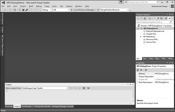
Step 8 − An empty project is created.
Step 9 − To make it a MFC project, right-click on the project and select Properties.
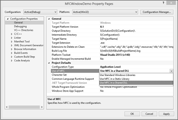
Step 10 − In the left section, click Configuration Properties → General.
Step 11 − Select the Use MFC in Shared DLL option in Project Defaults section and click OK.
Step 12 − Add a new source file.
Step 13 − Right-click on your Project and select Add → New Item.
Step 14 − In the Templates section, click C++ File (.cpp)
Step 15 − Set the Name as Example and click Add.
Step 16 − To create an application, we need to add a class and derive it from the MFC's CWinApp.
#include <afxwin.h>

class CExample : public CWinApp {
   public:
      BOOL InitInstance();
};
Dialog Box Creation
Step 1 − To create a dialog box, right-click on the Resource Files folder in solution explorer and select Add → Resource.
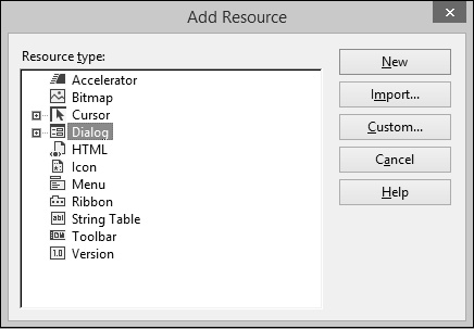
Step 2 − In the Add Resource dialog box, select Dialog and click New.
Step 3 − A dialog box requires some preparation before actually programmatically creating it.
Step 4 − A dialog box can first be manually created as a text file (in a resource file).
Step 5 − You can now see the MFCDialogDemo.rc file created under Resource Files.
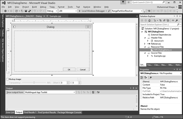
Step 6 − The resource file is open in designer. The same can be opened as a text file. Rightclick on the resource file and select Open With.
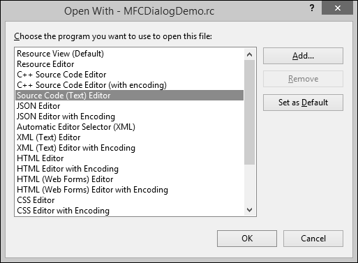
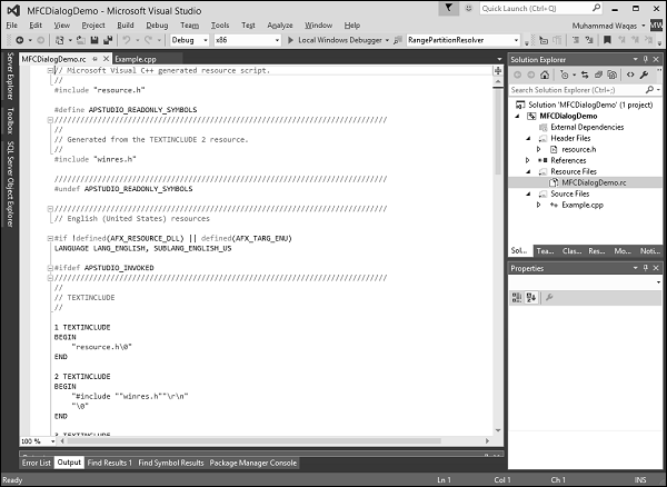
Step 7 − Select the Source Code (Text) editor and click Add button.
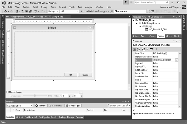
Step 8 − Go back to the designer and right-click on the dialog and select Properties.
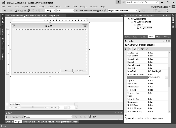
Step 9 − You need to choose out of the many options.
Step 10 − Like most other controls, a dialog box must be identified. The identifier (ID) of a dialog box usually starts with IDD_, Let us change the ID to IDD_EXAMPLE_DLG.
Dialog Location
A dialog box must be “physically” located on an application. Because a dialog box is usually created as a parent to other controls, its location depends on its relationship to its parent window or to the desktop.
If you look and the Properties window, you see two fields, X Pos and Y Pos.
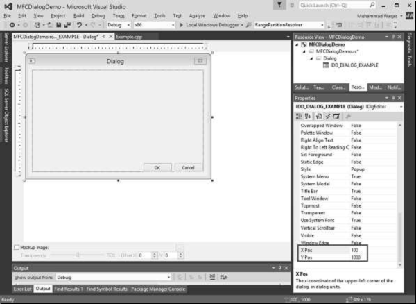
X is the distance from the left border of the monitor to the left border of the dialog box.
Y is the distance from the top border of the monitor to the top border of the dialog box.
By default, these fields are set to zero. You can also change as shown above.
If you specify these two dimensions as 0, the left and top borders of the dialog box would be set so the object appears in the center-middle of the screen.
Dialog Box Dimensions
The dimensions of a dialog box refer to its width and its height. You can resize the width and height with the help of mouse in designer window.
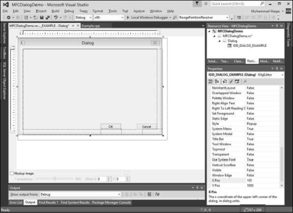
You can see the changes in width and height on the Status Bar.
Dialog Box Methods
The base class used for displaying dialog boxes on the screen is CDialog class. To create a dialog box, we need to derive a class from CDialog. The CDialog class itself provides three constructors which are as follows −
CDialog();
CDialog(UINT nIDTemplate, CWnd* pParentWnd = NULL);
CDialog(LPCTSTR lpszTemplateName, CWnd* pParentWnd = NULL);
Let us create another class CExampleDlg and derive it from CDialog. We will implement its default constructor destructor as shown in the following code.
class CExampleDlg : public CDialog {
   public:
      enum { IDD = IDD_EXAMPLE_DLG };

      CExampleDlg();
      ~CExampleDlg();
};

CExampleDlg::CExampleDlg():CDialog(CExampleDlg::IDD) {

}

CExampleDlg::~CExampleDlg() {

}
We need to instantiate this dialog on CExample::InitInstance() method as shown in the following code.
BOOL CExample::InitInstance() {
   CExampleDlg myDlg;
   m_pMainWnd = &myDlg;

   return TRUE;
}
Modal Dialog Boxes
There are two types of dialog boxes − modeless and modal. Modal and modeless dialog boxes differ by the process used to create and display them.
Modeless Dialog Box
For a modeless dialog box, you must provide your own public constructor in your dialog class.
To create a modeless dialog box, call your public constructor and then call the dialog object's Create member function to load the dialog resource.
You can call Create either during or after the constructor call. If the dialog resource has the property WS_VISIBLE, the dialog box appears immediately.
If not, you must call its ShowWindow member function.
Modal Dialog
To create a modal dialog box, call either of the two public constructors declared in CDialog.
Next, call the dialog object's DoModal member function to display the dialog box and manage interaction with it until the user chooses OK or Cancel.
This management by DoModal is what makes the dialog box modal. For modal dialog boxes, DoModal loads the dialog resource.
Step 1 − To display the dialog box as modal, in the CExample::InitInstance() event call the DoModal() method using your dialog variable −
BOOL CExample::InitInstance() {
   CExampleDlg myDlg;
   m_pMainWnd = &myDlg;
   myDlg.DoModal();
   return TRUE;
}
Step 2 − Here is the complete implementation of Example.cpp file.
#include <afxwin.h>
#include "resource.h"

class CExample : public CWinApp {
   public:
      BOOL InitInstance();
};

class CExampleDlg : public CDialog {
   public:
      enum { IDD = IDD_EXAMPLE_DLG };

      CExampleDlg();
     ~CExampleDlg();
};

CExampleDlg::CExampleDlg():CDialog(CExampleDlg::IDD) {

}

CExampleDlg::~CExampleDlg() {

}

BOOL CExample::InitInstance() {
   CExampleDlg myDlg;
   m_pMainWnd = &myDlg;
   myDlg.DoModal();
   return TRUE;
}
CExample MyApp;
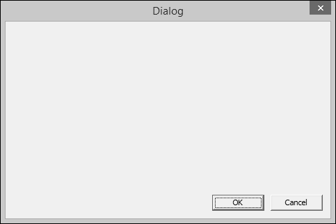
Step 3 − When the above code is compiled and executed, you will see the following dialog box.
Dialog-Based Applications
Microsoft Visual Studio provides an easier way to create an application that is mainly based on a dialog box. Here are the steps to create a dialog base project using project templates available in Visual Studio −
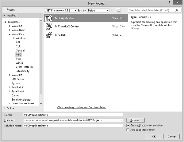
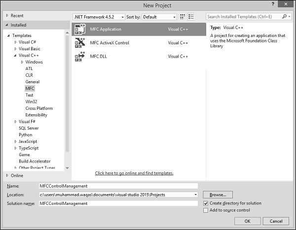
Step 1 − Open the Visual studio and click on the File → New → Project menu option. You can see the New Project dialog box.

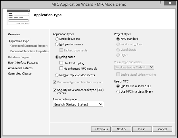
Step 2 − From the left pane, select Templates → Visual C++ → MFC.
Step 3 − In the middle pane, select MFC Application.
Step 4 − Enter project name ‘MFCModalDemo’ in the Name field and click OK to continue. You will see the following dialog box.
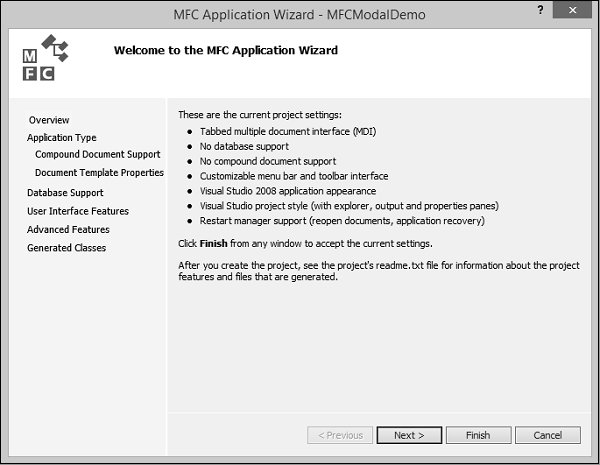
Step 5 − Click Next.
Step 6 − Select the options shown in the above dialog box and click Next.
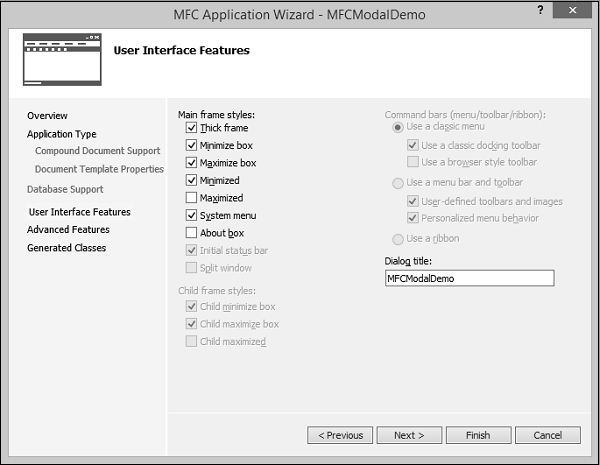
Step 7 − Check all the options that you choose to have on your dialog box like Maximize and Minimize Boxes and click Next.
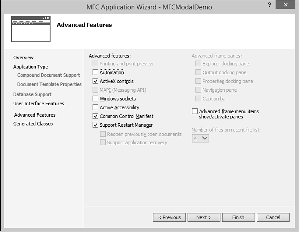
Step 8 − Click Next.
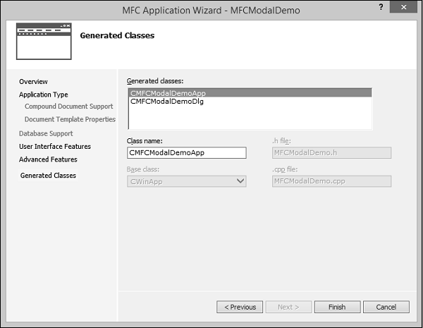
Step 9 − It will generate these two classes. You can change the name of the classes and click Finish.
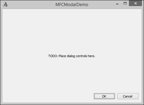
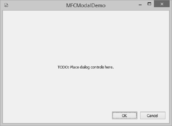
Step 10 − You can now see that the MFC wizard creates this Dialog Box and the project files by default.
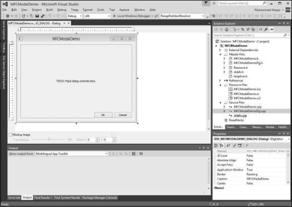
Step 11 − When you run this application, you will see the following output.
MFC - Windows Resources
A resource is a text file that allows the compiler to manage objects such as pictures, sounds, mouse cursors, dialog boxes, etc. Microsoft Visual Studio makes creating a resource file particularly easy by providing the necessary tools in the same environment used to program. This means, you usually do not have to use an external application to create or configure a resource file. Following are some important features related to resources.
Resources are interface elements that provide information to the user.
Bitmaps, icons, toolbars, and cursors are all resources.
Some resources can be manipulated to perform an action such as selecting from a menu or entering data in dialog box.
An application can use various resources that behave independently of each other, these resources are grouped into a text file that has the *.rc extension.
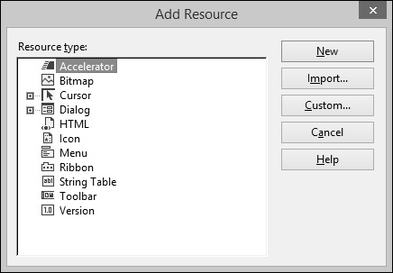
Most resources are created by selecting the desired one from the Add Resource dialog box.
The Add Resource dialog box provides an extensive list of resources which can be used as per requirements, but if you need something which is not available then you can add it manually to the *.rc file before executing the program.
Identifiers
An identifier is a symbol which is a constant integer whose name usually starts with ID. It consists of two parts − a text string (symbol name) mapped to an integer value (symbol value).
Symbols provide a descriptive way of referring to resources and user-interface objects, both in your source code and while you're working with them in the resource editors.
When you create a new resource or resource object, the resource editors provide a default name for the resource, for example, IDC_DIALOG1, and assign a value to it.
The name-plus-value definition is stored in the Resource.h file.
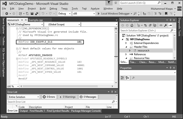
Step 1 − Let us look into our CMFCDialogDemo example from the last chapter in which we have created a dialog box and its ID is IDD_EXAMPLE_DLG.
Step 2 − Go to the Solution Explorer, you will see the resource.h file under Header Files. Continue by opening this file in editor and you will see the dialog box identifier and its integer value as well.
Icons
An icon is a small picture used on a window which represents an application. It is used in two main scenarios.
On a Window's frame, it is displayed on the left side of the Window name on the title bar.
In Windows Explorer, on the Desktop, in My Computer, or in the Control Panel window.
If you look at our MFCModalDemo example, you will see that Visual studio was using a default icon for the title bar as shown in the following snapshot.
You can create your own icon by following the steps given below −
Step 1 − Right-click on your project and select Add → Resources, you will see the Add Resources dialog box.

Step 2 − Select Icon and click New button and you will see the following icon.
Step 3 − In Solution Explorer, go to Resource View and expand MFCModalDemo > Icon. You will see two icons. The IDR_MAINFRAME is the default one and IDI_ICON1 is the newly created icon.
Step 4 − Right-click on the newly Created icon and select Properties.
Step 5 − IDI_ICON1 is the ID of this icon, now Let us change this ID to IDR_MYICON.
Step 6 − You can now change this icon in the designer as per your requirements. We will use the same icon.
Step 7 − Save this icon.
Step 8 − Go to the CMFCModalDemoDlg constructor in CMFCModalDemoDlg.cpp file which will look like the following code.
CMFCModalDemoDlg::CMFCModalDemoDlg(CWnd* pParent /* = NULL*/)
   : CDialogEx(IDD_MFCMODALDEMO_DIALOG, pParent) {
   m_hIcon = AfxGetApp() -> LoadIcon(IDR_MAINFRAME);
}
Step 9 − You can now see that the default icon is loaded in the constructor. Let us change it to IDR_ MYICON as shown in the following code.
CMFCModalDemoDlg::CMFCModalDemoDlg(CWnd* pParent /* = NULL*/)
   : CDialogEx(IDD_MFCMODALDEMO_DIALOG, pParent) {
   m_hIcon = AfxGetApp() -> LoadIcon(IDR_ MYICON);
}
Step 10 − When the above code is compiled and executed, you will see the new icon is displayed on the dialog box.
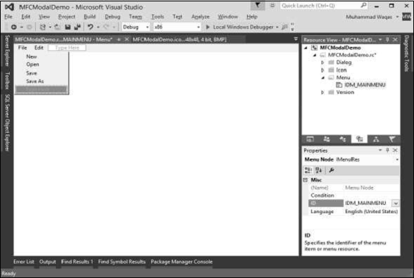
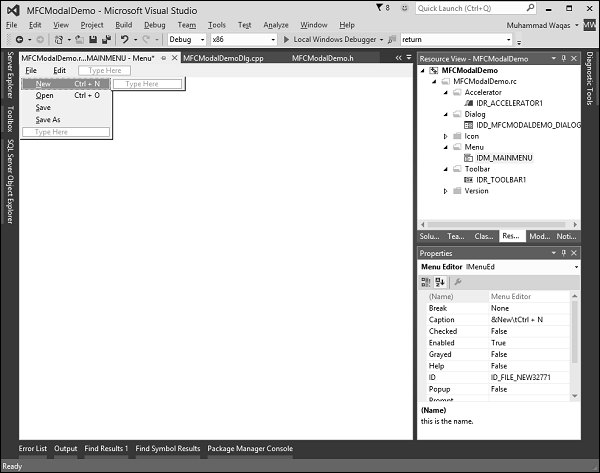
Menus
Menus allow you to arrange commands in a logical and easy-to-find fashion. With the Menu editor, you can create and edit menus by working directly with a menu bar that closely resembles the one in your finished application. To create a menu, follow the steps given below −
Step 1 − Right-click on your project and select Add → Resources. You will see the Add Resources dialog box.
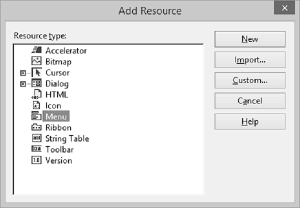
Step 2 − Select Menu and click New. You will see the rectangle that contains "Type Here" on the menu bar.
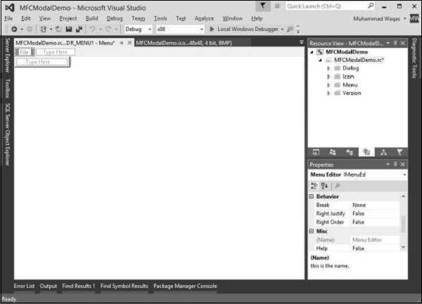
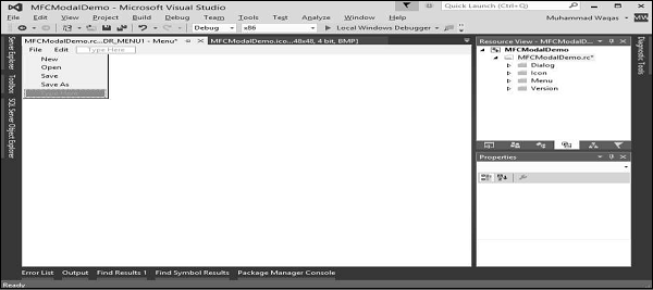
Step 3 − Write some menu options like File, Edit, etc. as shown in the following snapshot.
Step 4 − If you expand the Menu folder in Resource View, you will see the Menu identifier IDR_MENU1. Right-click on this identifier and change it to IDM_MAINMENU.
Step 5 − Save all the changes.
Step 6 − We need to attach this menu to our dialog box. Expand your Dialog folder in Solution Explorer and double click on the dialog box identifier.
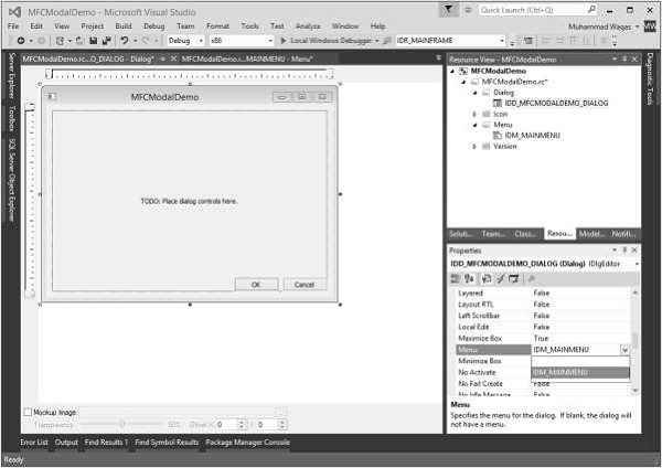
Step 7 − You will see the menu field in the Properties. Select the Menu identifier from the dropdown as shown above.
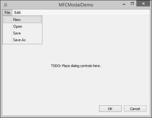
Step 8 − Run this application and you will see the following dialog box which also contains menu options.
Toolbars
A toolbar is a Windows control that allows the user to perform some actions on a form by clicking a button instead of using a menu.
A toolbar provides a convenient group of buttons that simplifies the user's job by bringing the most accessible actions as buttons.
A toolbar can bring such common actions closer to the user.
Toolbars usually display under the main menu.
They can be equipped with buttons but sometimes their buttons or some of their buttons have a caption.
Toolbars can also be equipped with other types of controls.
To create a toolbar, following are the steps.
Step 1 − Right-click on your project and select Add → Resources. You will see the Add Resources dialog box.
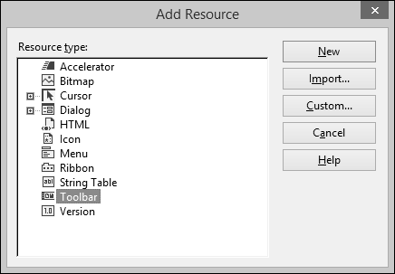
Step 2 − Select Toolbar and click New. You will see the following screen.
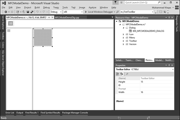
Step 3 − Design your toolbar in the designer as shown in the following screenshot and specify the IDs as well.
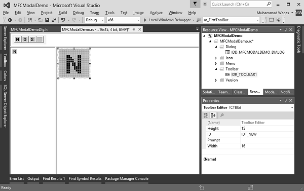
Step 4 − Add these two variables in CMFCModalDemoDlg class.
   CToolBar m_wndToolBar;
   BOOL butD;
Step 5 − Following is the complete implementation of CMFCModalDemoDlg in CMFCModalDemoDlg.h file −
class CMFCModalDemoDlg : public CDialogEx {
   // Construction
   public:
      CMFCModalDemoDlg(CWnd* pParent = NULL); // standard constructor
   // Dialog Data
   #ifdef AFX_DESIGN_TIME
      enum { IDD = IDD_MFCMODALDEMO_DIALOG };
   #endif

   protected:
      virtual void DoDataExchange(CDataExchange* pDX); // DDX/DDV support

   // Implementation
   protected:
      HICON m_hIcon;
      CToolBar m_wndToolBar;
      BOOL butD;

      // Generated message map functions
      virtual BOOL OnInitDialog();
      afx_msg void OnPaint();
      afx_msg HCURSOR OnQueryDragIcon();
      DECLARE_MESSAGE_MAP()

   public:
      afx_msg void OnBnClickedOk();
};
Step 6 − Update CMFCModalDemoDlg::OnInitDialog() as shown in the following code.
BOOL CMFCModalDemoDlg::OnInitDialog() {
   CDialogEx::OnInitDialog();

   // Set the icon for this dialog. The framework does this automatically
   // when the application's main window is not a dialog
   SetIcon(m_hIcon, TRUE);       // Set big icon
   SetIcon(m_hIcon, FALSE);      // Set small icon

   if (!m_wndToolBar.Create(this)
      || !m_wndToolBar.LoadToolBar(IDR_TOOLBAR1))
      //if (!m_wndToolBar.CreateEx(this, TBSTYLE_FLAT, WS_CHILD |
      // WS_VISIBLE | CBRS_TOP | CBRS_GRIPPER | CBRS_TOOLTIPS |
      // CBRS_FLYBY | CBRS_SIZE_DYNAMIC) ||
      // !m_wndToolBar.LoadToolBar(IDR_TOOLBAR1)) {
         TRACE0("Failed to Create Dialog Toolbar\n");
         EndDialog(IDCANCEL);
      }
      butD = TRUE;
      CRect rcClientOld; // Old Client Rect
      CRect rcClientNew; // New Client Rect with Tollbar Added

      // Retrive the Old Client WindowSize
      // Called to reposition and resize control bars in the client area of a window
      // The reposQuery FLAG does not really traw the Toolbar. It only does the calculations.
      // And puts the new ClientRect values in rcClientNew so we can do the rest of the Math.

      GetClientRect(rcClientOld);
      RepositionBars(AFX_IDW_CONTROLBAR_FIRST, AFX_IDW_CONTROLBAR_LAST, 0, reposQuery, rcClientNew);
      // All of the Child Windows (Controls) now need to be moved so the Tollbar does not cover them up.
      // Offest to move all child controls after adding Tollbar
      CPoint ptOffset(rcClientNew.left - rcClientOld.left, rcClientNew.top - rcClientOld.top);

      CRect rcChild;
      CWnd* pwndChild = GetWindow(GW_CHILD); //Handle to the Dialog Controls

      while (pwndChild) // Cycle through all child controls {
         pwndChild -> GetWindowRect(rcChild); // Get the child control RECT
         ScreenToClient(rcChild);

         // Changes the Child Rect by the values of the claculated offset
         rcChild.OffsetRect(ptOffset);
         pwndChild -> MoveWindow(rcChild, FALSE); // Move the Child Control
         pwndChild = pwndChild -> GetNextWindow();
      }

      CRect rcWindow;
      // Get the RECT of the Dialog
      GetWindowRect(rcWindow);

      // Increase width to new Client Width
      rcWindow.right += rcClientOld.Width() - rcClientNew.Width();

      // Increase height to new Client Height
       rcWindow.bottom += rcClientOld.Height() - rcClientNew.Height();
      // Redraw Window
      MoveWindow(rcWindow, FALSE);

      // Now we REALLY Redraw the Toolbar
      RepositionBars(AFX_IDW_CONTROLBAR_FIRST, AFX_IDW_CONTROLBAR_LAST, 0);

   // TODO: Add extra initialization here

   return TRUE; // return TRUE unless you set the focus to a control
}
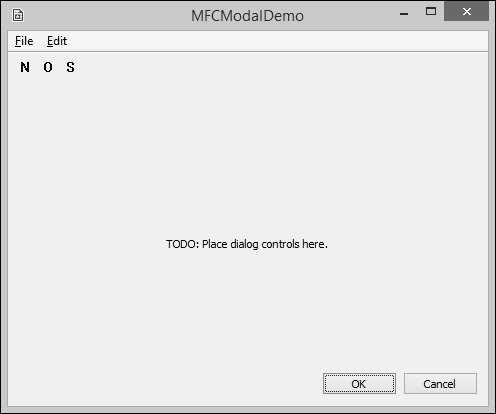
Step 7 − Run this application. You will see the following dialog box which also contains the toolbar.
Accelerators
An access key is a letter that allows the user to perform a menu action faster by using the keyboard instead of the mouse. This is usually faster because the user would not need to position the mouse anywhere, which reduces the time it takes to perform the action.
Step 1 − To create an access key, type an ampersand "&" on the left of the menu item.
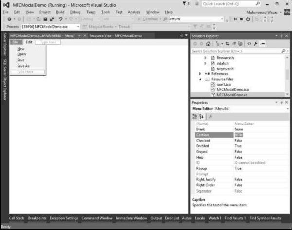
Step 2 − Repeat this step for all menu options. Run this application and press Alt. You will see that the first letter of all menu options are underlined.
Shortcut Key
A shortcut key is a key or a combination of keys used by advanced users to perform an action that would otherwise be done on a menu item. Most shortcuts are a combination of the Ctrl key simultaneously pressed with a letter key. For example, Ctrl + N, Ctrl + O, or Ctrl + D.
To create a shortcut, on the right side of the string that makes up a menu caption, rightclick on the menu item and select properties.
In the Caption field type \t followed by the desired combination as shown below for the New menu option. Repeat the step for all menu options.
Accelerator Table
An Accelerator Table is a list of items where each item of the table combines an identifier, a shortcut key, and a constant number that specifies the kind of accelerator key. Just like the other resources, an accelerator table can be created manually in a .rc file. Following are the steps to create an accelerator table.
Step 1 − To create an accelerator table, right-click on *.rc file in the solution explorer.
Step 2 − Select Accelerator and click New.

Step 3 − Click the arrow of the ID combo box and select menu Items.
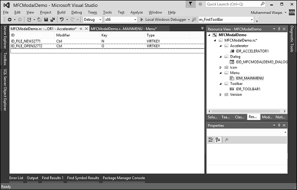
Step 4 − Select Ctrl from the Modifier dropdown.
Step 5 − Click the Key box and type the respective Keys for both menu options.
We will also add New menu item event handler to testing. Right-click on the New menu option.
Step 6 − You can specify a class, message type and handler name. For now, let us leave it as it is and click Add and Edit button.
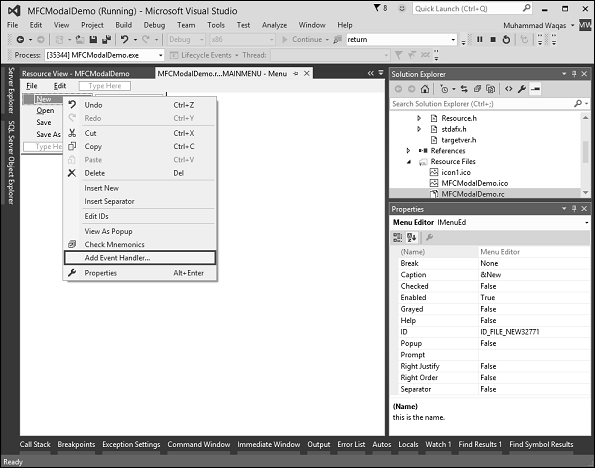
Step 7 − Select Add Event Handler.
Step 8 − You will now see the event added at the end of the CMFCModalDemoDlg.cpp file.
void CMFCModalDemoDlg::OnFileNew() {
// TODO: Add your command handler code here
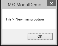
MessageBox(L"File > New menu option");
}
Step 9 − Now Let us add a message box that will display the simple menu option message.
To start accelerator table in working add the HACCEL variable and ProcessMessageFilter as shown in the following CMFCModalDemoApp.
class CMFCModalDemoApp : public CWinApp {
   public:
      CMFCModalDemoApp();

   // Overrides
   public:
      virtual BOOL InitInstance();
      HACCEL m_hAccelTable;

      // Implementation

      DECLARE_MESSAGE_MAP()
      virtual BOOL ProcessMessageFilter(int code, LPMSG lpMsg);
};
Step 10 − Load Accelerator and the following call in the CMFCModalDemoApp::InitInstance().
m_hAccelTable = LoadAccelerators(AfxGetInstanceHandle(),
   MAKEINTRESOURCE(IDR_ACCELERATOR1));
Step 11 − Here is the implementation of ProcessMessageFilter.
BOOL CMFCModalDemoApp::ProcessMessageFilter(int code, LPMSG lpMsg) {
   if (code >= 0 && m_pMainWnd && m_hAccelTable) {
      if (::TranslateAccelerator(m_pMainWnd -> m_hWnd, m_hAccelTable, lpMsg))
      return TRUE;
   }
   return CWinApp::ProcessMessageFilter(code, lpMsg);
}
Step 12 − When the above code is compiled and executed, you will see the following output.
Step 13 − Press Alt button followed by F key and then N key or Ctrl + N. You will see the following message.
MFC - Property Sheets
A property sheet, also known as a tab dialog box, is a dialog box that contains property pages. Each property page is based on a dialog template resource and contains controls. It is enclosed on a page with a tab on top. The tab names the page and indicates its purpose. Users click a tab in the property sheet to select a set of controls.
To create property pages, let us look into a simple example by creating a dialog based MFC project.
Once the project is created, we need to add some property pages.
Visual Studio makes it easy to create resources for property pages by displaying the Add Resource dialog box, expanding the Dialog node and selecting one of the IDD_PROPPAGE_X items.
Step 1 − Right-click on your project in solution explorer and select Add → Resources.
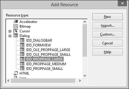
Step 2 − Select the IDD_PROPPAGE_LARGE and click NEW.
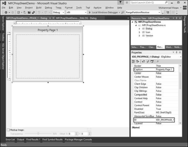
Step 3 − Let us change ID and Caption of this property page to IDD_PROPPAGE_1 and Property Page 1 respectively as shown above.
Step 4 − Right-click on the property page in designer window.
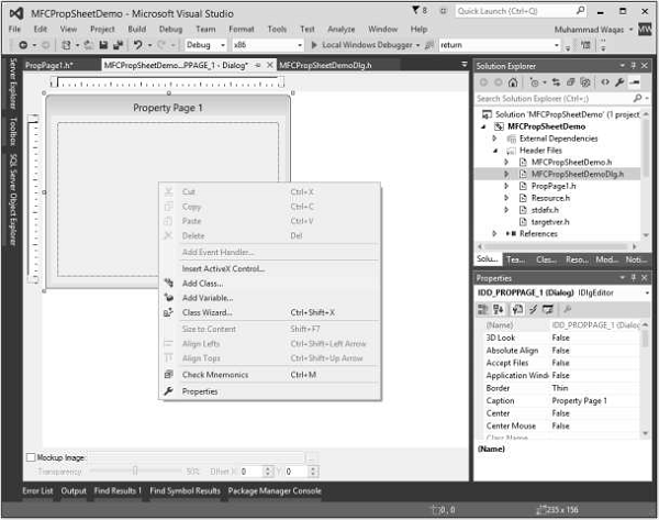
Step 5 − Select the Add Class option.
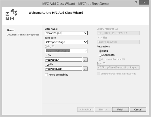
Step 6 − Enter the class name and select CPropertyPage from base class dropdown list.
Step 7 − Click Finish to continue.
Step 8 − Add one more property page with ID IDD_PROPPAGE_2 and Caption Property Page 2 by following the above mentioned steps.
Step 9 − You can now see two property pages created. To implement its functionality, we need a property sheet.
The Property Sheet groups the property pages together and keeps it as entity.
To create a property sheet, follow the steps given below −
Step 1 − Right-click on your project and select Add > Class menu options.
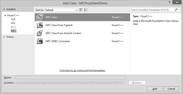
Step 2 − Select Visual C++ → MFC from the left pane and MFC Class in the template pane and click Add.
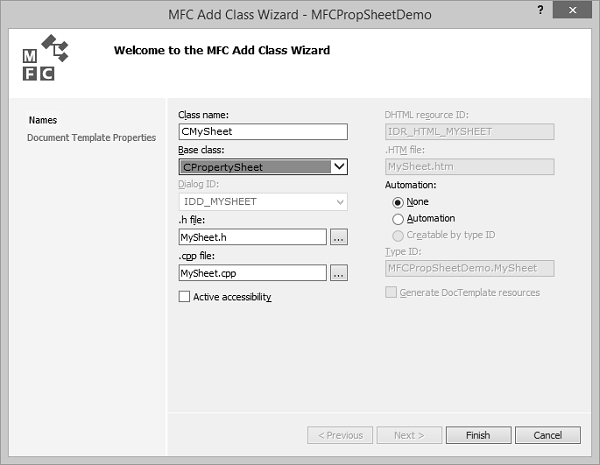
Step 3 − Enter the class name and select CPropertySheet from base class dropdown list.
Step 4 − Click finish to continue.
Step 5 − To launch this property sheet, we need the following changes in our main project class.
Step 6 − Add the following references in CMFCPropSheetDemo.cpp file.
#include "MySheet.h"
#include "PropPage1.h"
#include "PropPage2.h"
Step 7 − Modify the CMFCPropSheetDemoApp::InitInstance() method as shown in the following code.
CMySheet mySheet(L"Property Sheet Demo");
CPropPage1 page1;
CPropPage2 page2;

mySheet.AddPage(&page1);
mySheet.AddPage(&page2);

m_pMainWnd = &mySheet;
INT_PTR nResponse = mySheet.DoModal();
Step 8 − Here is the complete implementation of CMFCPropSheetDemo.cpp file.
// MFCPropSheetDemo.cpp : Defines the class behaviors for the application.
//
#include "stdafx.h"
#include "MFCPropSheetDemo.h"
#include "MFCPropSheetDemoDlg.h"
#include "MySheet.h"
#include "PropPage1.h"
#include "PropPage2.h"

#ifdef _DEBUG
#define new DEBUG_NEW
#endif


// CMFCPropSheetDemoApp
BEGIN_MESSAGE_MAP(CMFCPropSheetDemoApp, CWinApp)
   ON_COMMAND(ID_HELP, &CWinApp::OnHelp)
END_MESSAGE_MAP()


// CMFCPropSheetDemoApp construction

CMFCPropSheetDemoApp::CMFCPropSheetDemoApp() {

   // support Restart Manager
   m_dwRestartManagerSupportFlags = AFX_RESTART_MANAGER_SUPPORT_RESTART;
   // TODO: add construction code here,
   // Place all significant initialization in InitInstance
}


// The one and only CMFCPropSheetDemoApp object

CMFCPropSheetDemoApp theApp;


// CMFCPropSheetDemoApp initialization

BOOL CMFCPropSheetDemoApp::InitInstance() {

   // InitCommonControlsEx() is required on Windows XP if an application
   // manifest specifies use of ComCtl32.dll version 6 or later to enable
   // visual styles. Otherwise, any window creation will fail.
   INITCOMMONCONTROLSEX InitCtrls;
   InitCtrls.dwSize = sizeof(InitCtrls);
   // Set this to include all the common control classes you want to use
   // in your application.
   InitCtrls.dwICC = ICC_WIN95_CLASSES;
   InitCommonControlsEx(&InitCtrls);

   CWinApp::InitInstance();


   AfxEnableControlContainer();

   // Create the shell manager, in case the dialog contains
   // any shell tree view or shell list view controls.
   CShellManager *pShellManager = new CShellManager;

   // Activate "Windows Native" visual manager for enabling themes in MFC controls
   CMFCVisualManager::SetDefaultManager(RUNTIME_CLASS(CMFCVisualManagerWindows));
   // Standard initialization
   // If you are not using these features and wish to reduce the size
   // of your final executable, you should remove from the following
   // the specific initialization routines you do not need
   // Change the registry key under which our settings are stored
   // TODO: You should modify this string to be something appropriate
   // such as the name of your company or organization
   SetRegistryKey(_T("Local AppWizard-Generated Applications"));

   CMySheet mySheet(L"Property Sheet Demo");
   CPropPage1 page1;
   CPropPage2 page2;

   mySheet.AddPage(&page1);
   mySheet.AddPage(&page2);

   m_pMainWnd = &mySheet;
   INT_PTR nResponse = mySheet.DoModal();
   if (nResponse == IDOK) {
      // TODO: Place code here to handle when the dialog is
      // dismissed with OK
   }else if (nResponse == IDCANCEL) {
      // TODO: Place code here to handle when the dialog is
      // dismissed with Cancel
   }else if (nResponse == -1) {
      TRACE(traceAppMsg, 0, "Warning: dialog creation failed,
        so application is terminating unexpectedly.\n");
      TRACE(traceAppMsg, 0, "Warning: if you are using MFC controls on the dialog,
        you cannot #define _AFX_NO_MFC_CONTROLS_IN_DIALOGS.\n");
   }

   // Delete the shell manager created above.
   if (pShellManager != NULL) {
      delete pShellManager;
   }

   // Since the dialog has been closed, return FALSE so that we exit the
   // application, rather than start the application's message pump.
   return FALSE;
}
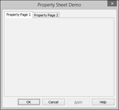
Step 9 − When the above code is compiled and executed, you will see the following dialog box. This dialog box contains two property pages.
MFC - Windows Layout
Layout of controls is very important and critical for application usability. It is used to arrange a group of GUI elements in your application. There are certain important things to consider while selecting layout −
- Positions of the child elements.
- Sizes of the child elements.
Adding controls
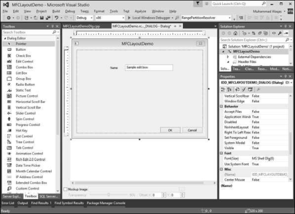
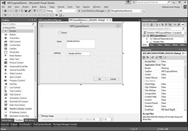
Let us create new Dialog based MFC Project MFCLayoutDemo.
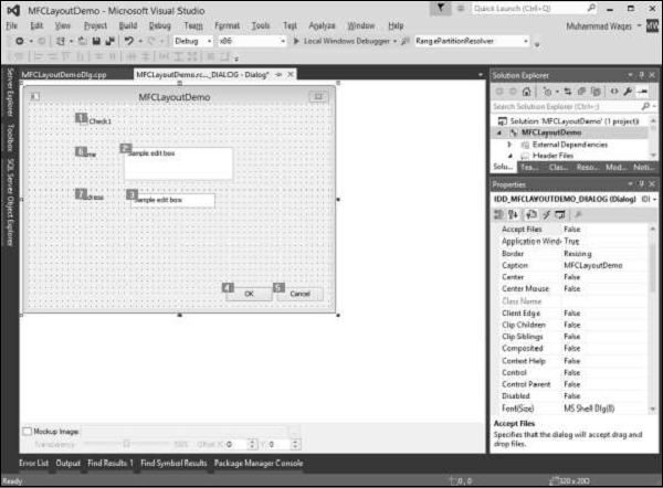
Step 1 − Once the project is created, you will see the following screen.
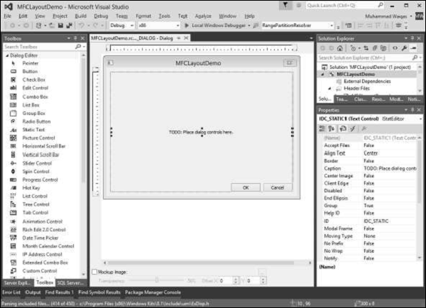
Step 2 − Delete the TODO from the dialog box.
Step 3 − Drag some controls from the Toolbox which you can see on the left side.
(We will drag one Static Text and one Edit Control as shown in the following snapshot).
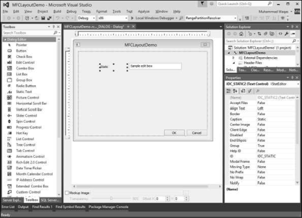
Step 4 − Change the Caption of the Static Text to Name.
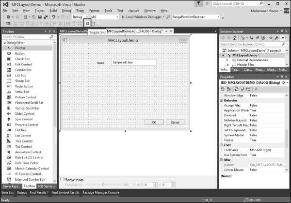
Control Grid
Control grid is the guiding grid dots, which can help in positioning of the controls you are adding at the time of designing.
To enable the control grid, you need to click the Toggle Grid button in the toolbar as shown in the following snapshot.
Controls Resizing
After you have added a control to a dialog box, it assumes either its default size or the size you drew it with. To help with the sizes of controls on the form or dialog box, Visual Studio provides a visual grid made of black points.
To resize a control, that is, to give it a particular width or height, position the mouse on one of the handles and drag it in the desired direction.

You can now resize the controls with the help of this dotted grid.
Controls Positions
The controls you position on a dialog box or a form assume their given place. Most of the time, these positions are not practical. You can move them around to any position of your choice.
Let us add some more controls −
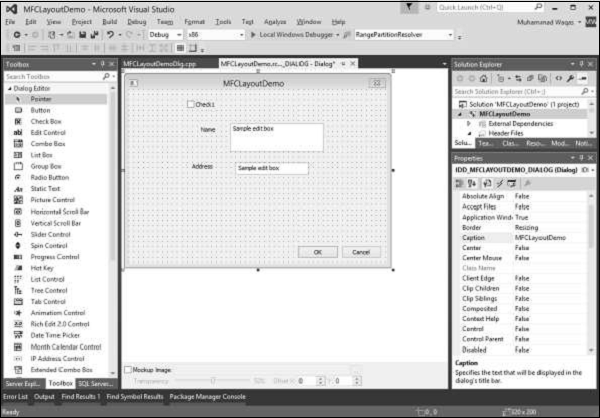
Step 1 − To move a control, click and drag it in the desired direction until it reaches the intended position.
Step 2 − To move a group of controls, first select them. Then drag the selection to the desired location. Let us select the Static Texts and Edit Controls.
Step 3 − Move these selected controls to the left side.

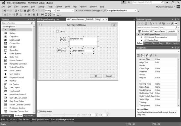
To help with positioning the controls, Visual Studio provides the Dialog toolbar with the following buttons.
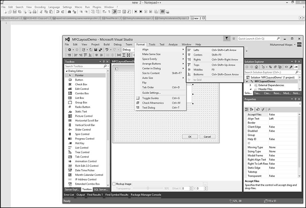
Step 1 − Let us align the Check box and Static Text controls to the left by selecting all these controls.
Step 2 − Select the Format → Align → Lefts.
Step 3 − You can now see all these controls are aligned to the left.
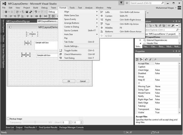
Tab Ordering
The controls you add to a form or a dialog box are positioned in a sequence that follows the order they were added. When you add control(s) regardless of the section or area you place the new control, it is sequentially positioned at the end of the existing controls. If you do not fix it, the user would have a hard time navigating the controls. The sequence of controls navigation is also known as the tab order.
To change the tab, you can either use the Format → Tab Order menu option or you can also use the Ctrl + D shortcut. Let us press Ctrl + D.

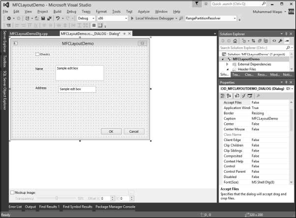
You can now see the order in which all these controls are added to this dialog box. To Change the order or sequence of controls, click on all the controls in sequence in which you want to navigate.
In this example, we will first click on the checkbox followed by Name and Address Edit controls. Then click OK and Cancel as shown in the following snapshot.
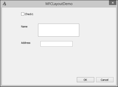
Let us run this application and you will see the following output.
MFC - Controls Management
In MFC applications, after visually adding a control to your application, if you want to refer to it in your code, you can declare a variable based on, or associated with that control. The MFC library allows you to declare two types of variables for some of the controls used in an application a value or a control variable.
One variable is used for the information stored in the control, which is also known as Control Variable/Instance.
The other variable is known as Control Value Variable. A user can perform some sort of actions on that control with this variable.
Control Variable/Instance
A control variable is a variable based on the class that manages the control. For example, a button control is based on the CButton class.
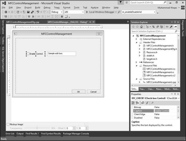
To see these concepts in real programming, let us create an MFC dialog based project MFCControlManagement.
Once the project is created, you will see the following dialog box in designer window.
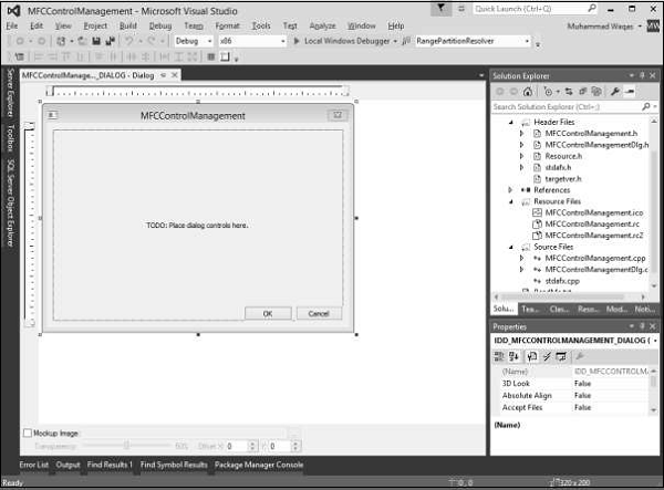
Step 1 − Delete the TODO line and drag one checkbox and one Edit control as shown in the following snapshot. Change the caption of checkbox to Enable Control.
Step 2 − Right-click on the checkbox.
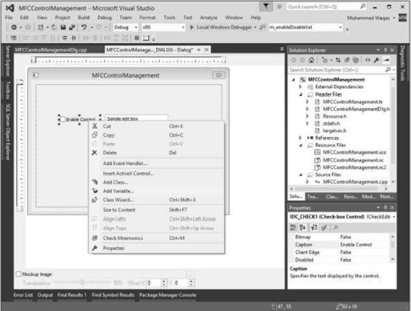
Step 3 − Select Add Variable.
Step 4 − You can now see the Add Member Variable Wizard.
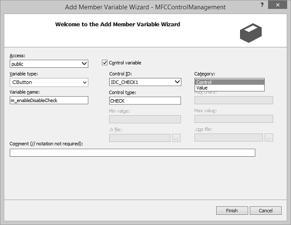
You can select different options on this dialog box. For checkbox, the variable type is CButton. It is selected by default in this dialog box.
Similarly, the control ID is also selected by default now we need to select Control in the Category combo box, and type m_enableDisableCheck in the Variable Name edit box and click finish.
Step 5 − Similarly, add Control Variable of Edit control with the settings as shown in the following snapshot.

Observe the header file of the dialog class. You can see that the new variables have been added now.
CButton m_enableDisableCheck;
CEdit m_myEditControl;
Control Value Variable
Another type of variable you can declare for a control is the value variable. Not all controls provide a value variable.
The value variable must be able to handle the type of value stored in the control it is intended to refer to.
For example, because a text based control is used to handle text, you can declare a text-based data type for it. This would usually be a CString variable.
Let us look into this type of variable for checkbox and edit control.
Step 1 − Right-click on the checkbox and select Add Variable.
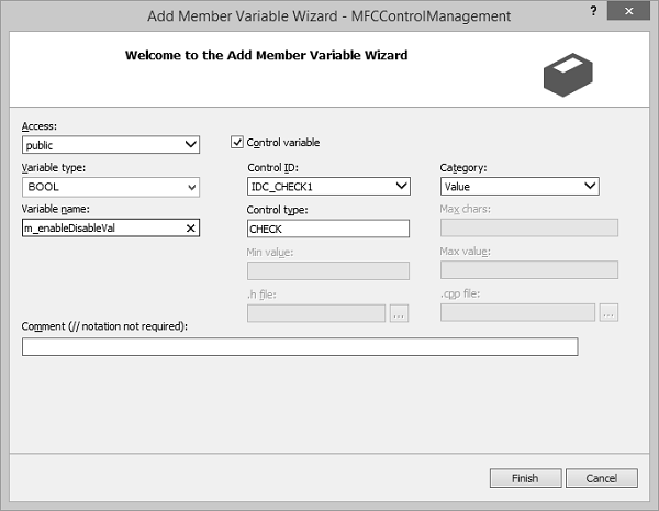
Step 2 − The Variable type is BOOL. Select Value from the Category dropdown list.
Step 3 − Click Finish to continue.
Step 4 − Similarly, add value Variable for Edit control with the settings as shown in the following snapshot.

Step 5 − Type CString in variable type and m_editControlVal in the variable name field.
Step 6 − You can now see these variables added in the Header file.
bool m_enableDisableVal;
CString m_editControlVal;
Controls Event Handlers
After adding a control to your application, whether you visually added it or created it dynamically, you will also decide how to handle the possible actions that the user can perform on the control.
For project dialog boxes that are already associated with a class, you can take advantage of some shortcuts when you create event handlers.
You can quickly create a handler either for the default control notification event or for any applicable Windows message.
Let us look into the same example in which we added event handler for checkbox.
Step 1 − Right-click the control for which you want to handle the notification event.
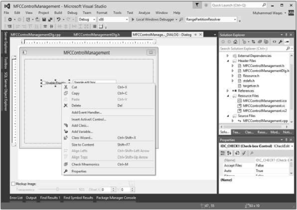
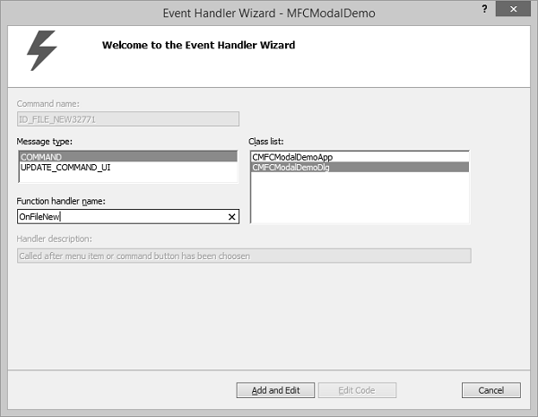
Step 2 − On the shortcut menu, click Add Event Handler to display the Event Handler Wizard.
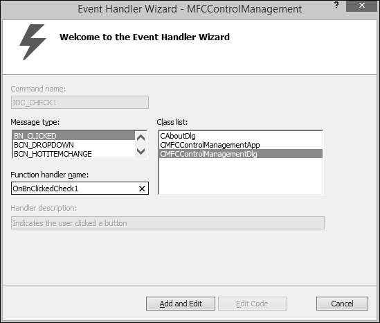
Step 3 − Select the event in the Message type box to add to the class selected in the Class list box.
Step 4 − Accept the default name in the Function handler name box, or provide the name of your choice.
Step 5 − Click Add and edit to add the event handler.
Step 6 − You can now see the following event added at the end of CMFCControlManagementDlg.cpp file.
void CMFCControlManagementDlg::OnBnClickedCheck1() {
   // TODO: Add your control notification handler code here
}
Controls Management
So far, we have seen how to add controls to an application. We will now see how to manage these controls as per user requirement. We can use the control variable/instance in a particular event handler.
Step 1 − Let us look into the following example. Here, we will enable/disable the edit control when the checkbox is checked/unchecked.
Step 2 − We have now added the checkbox click event handler. Here is the implementation −
void CMFCControlManagementDlg::OnBnClickedCheck1() {
   // TODO: Add your control notification handler code here
   UpdateData(TRUE);
   if (m_enableDisableVal)
      m_myEditControl.EnableWindow(TRUE);
   else
      m_myEditControl.EnableWindow(FALSE);
}
Step 3 − When the dialog is created, we need to add the following code to CMFCControlManagementDlg::OnInitDialog(). This will manage these controls.
UpdateData(TRUE);
if (m_enableDisableVal)
   m_myEditControl.EnableWindow(TRUE);
else
   m_myEditControl.EnableWindow(FALSE);
Step 4 − Here is the complete implementation of CMFCControlManagementDlg.cpp file.
// MFCControlManagementDlg.cpp : implementation file
//

#include "stdafx.h"
#include "MFCControlManagement.h"
#include "MFCControlManagementDlg.h"
#include "afxdialogex.h"

#ifdef _DEBUG
#define new DEBUG_NEW
#endif


// CAboutDlg dialog used for App About

class CAboutDlg : public CDialogEx {
   public:
      CAboutDlg();

   // Dialog Data
   #ifdef AFX_DESIGN_TIME
      enum { IDD = IDD_ABOUTBOX };
   #endif

   protected:
      virtual void DoDataExchange(CDataExchange* pDX); // DDX/DDV support

   // Implementation
   protected:
      DECLARE_MESSAGE_MAP()
};

CAboutDlg::CAboutDlg() : CDialogEx(IDD_ABOUTBOX) {

}
void CAboutDlg::DoDataExchange(CDataExchange* pDX) {
   CDialogEx::DoDataExchange(pDX);
}

BEGIN_MESSAGE_MAP(CAboutDlg, CDialogEx)
END_MESSAGE_MAP()

// CMFCControlManagementDlg dialog


CMFCControlManagementDlg::CMFCControlManagementDlg(CWnd* pParent /* = NULL*/)
   :CDialogEx(IDD_MFCCONTROLMANAGEMENT_DIALOG, pParent) ,
   m_enableDisableVal(FALSE) , m_editControlVal(_T("")) {
   m_hIcon = AfxGetApp()&rarr LoadIcon(IDR_MAINFRAME);
}

void CMFCControlManagementDlg::DoDataExchange(CDataExchange* pDX) {
   CDialogEx::DoDataExchange(pDX);
   DDX_Control(pDX, IDC_CHECK1, m_enableDisableCheck);
   DDX_Control(pDX, IDC_EDIT1, m_myEditControl);
   DDX_Check(pDX, IDC_CHECK1, m_enableDisableVal);
   DDX_Text(pDX, IDC_EDIT1, m_editControlVal);
}
BEGIN_MESSAGE_MAP(CMFCControlManagementDlg, CDialogEx)
   ON_WM_SYSCOMMAND()
   ON_WM_PAINT()
   ON_WM_QUERYDRAGICON()
   ON_BN_CLICKED(IDC_CHECK1, &CMFCControlManagementDlg::OnBnClickedCheck1)
END_MESSAGE_MAP()

// CMFCControlManagementDlg message handlers

BOOL CMFCControlManagementDlg::OnInitDialog() {
   CDialogEx::OnInitDialog();

   // Add "About..." menu item to system menu.
   // IDM_ABOUTBOX must be in the system command range.
   ASSERT((IDM_ABOUTBOX & 0xFFF0) == IDM_ABOUTBOX);
   ASSERT(IDM_ABOUTBOX < 0xF000);

   CMenu* pSysMenu = GetSystemMenu(FALSE);
   if (pSysMenu != NULL) {
      BOOL bNameValid;
      CString strAboutMenu;
      bNameValid = strAboutMenu.LoadString(IDS_ABOUTBOX);
      ASSERT(bNameValid);
      if (!strAboutMenu.IsEmpty()) {
         pSysMenu → AppendMenu(MF_SEPARATOR);
         pSysMenu → AppendMenu(MF_STRING, IDM_ABOUTBOX, strAboutMenu);
      }
   }

   // Set the icon for this dialog. The framework does this automatically
   // when the application's main window is not a dialog
   SetIcon(m_hIcon, TRUE);        // Set big icon
   SetIcon(m_hIcon, FALSE);       // Set small icon

   // TODO: Add extra initialization here
   UpdateData(TRUE);
   if (m_enableDisableVal)
      m_myEditControl.EnableWindow(TRUE);
   else
      m_myEditControl.EnableWindow(FALSE);
   return TRUE; // return TRUE unless you set the focus to a control
}
void CMFCControlManagementDlg::OnSysCommand(UINT nID, LPARAM lParam) {
   if ((nID & 0xFFF0) == IDM_ABOUTBOX) {
      CAboutDlg dlgAbout;
      dlgAbout.DoModal();
   }else {
      CDialogEx::OnSysCommand(nID, lParam);
   }
}

// If you add a minimize button to your dialog, you will need the code below
// to draw the icon. For MFC applications using the document/view model,
// this is automatically done for you by the framework.

void CMFCControlManagementDlg::OnPaint() {
   if (IsIconic()) {
      CPaintDC dc(this); // device context for painting

      SendMessage(WM_ICONERASEBKGND,
         reinterpret_cast<WPARAM>(dc.GetSafeHdc()), 0);

      // Center icon in client rectangle
      int cxIcon = GetSystemMetrics(SM_CXICON);
      int cyIcon = GetSystemMetrics(SM_CYICON);
      CRect rect;
      GetClientRect(&rect);
      int x = (rect.Width() - cxIcon + 1) / 2;
      int y = (rect.Height() - cyIcon + 1) / 2;

      // Draw the icon
      dc.DrawIcon(x, y, m_hIcon);
   }else {
      CDialogEx::OnPaint();
   }
}

// The system calls this function to obtain the cursor to display while the user drags
// the minimized window.
HCURSOR CMFCControlManagementDlg::OnQueryDragIcon() {
   return static_cast<HCURSOR>(m_hIcon);
}

void CMFCControlManagementDlg::OnBnClickedCheck1() {
   // TODO: Add your control notification handler code here
   UpdateData(TRUE);
   if (m_enableDisableVal)
      m_myEditControl.EnableWindow(TRUE);
   else
      m_myEditControl.EnableWindow(FALSE);
}
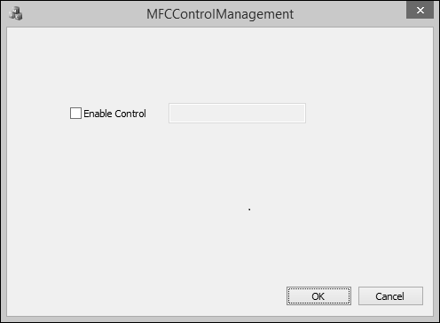
Step 5 − When the above code is compiled and executed, you will see the following output. The checkbox is unchecked by default. This disables the edit control too.
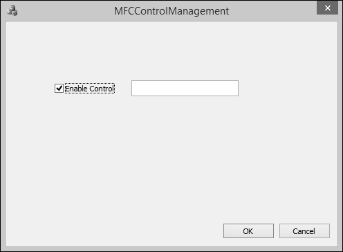
Step 6 − Check the Enable Control checkbox. This will automatically enable the edit control.
MFC - Windows Control
Windows controls are objects that users can interact with to enter or manipulate data. They commonly appear in dialog boxes or on toolbars. There are various types of controls −
A text based control which is used to display text to the user or request text from the user.
A list based control displays a list of items.
A progress based control is used to show the progress of an action.
A static control can be used to show colors, a picture or something that does not regularly fit in the above categories.
| Sr.No. | Controls & Description |
|---|---|
| 1 | Static Control
A static control is an object that displays information to the user without his or her direct intervention. It can be used to show colors, a geometric shape, or a picture such as an icon, a bitmap, or an animation. |
| 2 | Animation Control
An animation control is a window that displays an Audio clip in AVI format. An AVI clip is a series of bitmap frames, like a movie. Animation controls can only play simple AVI clips, and they do not support sound. It is represented by the CAnimateCtrl class. |
| 3 | Button
A button is an object that the user clicks to initiate an action. Button control is represented by CButton class. |
| 4 | Bitmap Button
A bitmap button displays a picture or a picture and text on its face. This is usually intended to make the button a little explicit. A bitmap button is created using the CBitmapButton class, which is derived from CButton. |
| 5 | Command Button
A command button is an enhanced version of the regular button. It displays a green arrow icon on the left, followed by a caption in regular size. Under the main caption, it can display another smaller caption that serves as a hint to provide more information. |
| 6 | Static Text
A static control displays a text string, box, rectangle, icon, cursor, bitmap, or enhanced metafile. It is represented by CStatic class. It can be used to label, box, or separateother controls. A static control normally takes no input and provides no output. |
| 7 | List Box
A list box displays a list of items, such as filenames, that the user can view and select. A List box is represented by CListBox class. In a single-selection list box, the user can select only one item. In a multiple-selection list box, a range of items can be selected. When the user selects an item, it is highlighted and the list box sends a notification message to the parent window. |
| 8 | Combo Boxes
A combo box consists of a list box combined with either a static control or edit control. it is represented by CComboBox class. The list-box portion of the control may be displayed at all times or may only drop down when the user selects the drop-down arrow next to the control. |
| 9 | Radio Buttons
A radio button is a control that appears as a dot surrounded by a round box. In reality, a radio button is accompanied by one or more other radio buttons that appear and behave as a group. |
| 10 | Checkboxes
A checkbox is a Windows control that allows the user to set or change the value of an item as true or false. |
| 11 | Image Lists
An Image List is a collection of same-sized images, each of which can be referred to by its zero-based index. Image lists are used to efficiently manage large sets of icons or bitmaps. Image lists are represented by CImageList class. |
| 12 | Edit Box
An Edit Box is a rectangular child window in which the user can enter text. It is represented by CEdit class. |
| 13 | Rich Edit
A Rich Edit Control is a window in which the user can enter and edit text. The text can be assigned character and paragraph formatting, and can include embedded OLE objects. It is represented by CRichEditCtrl class. |
| 14 | Group Box
A group box is a static control used to set a visible or programmatic group of controls. The control is a rectangle that groups other controls together. |
| 15 | Spin Button
A Spin Button Control (also known as an up-down control) is a pair of arrow buttons that the user can click to increment or decrement a value, such as a scroll position or a number displayed in a companion control. it is represented by CSpinButtonCtrl class. |
| 16 | Managing the Updown Control
It manages the Updown Controls. |
| 17 | Progress Control
A progress bar control is a window that an application can use to indicate the progress of a lengthy operation. It consists of a rectangle that is gradually filled, from left to right, with the system highlight color as an operation progresses. It is represented by CProgressCtrl class. |
| 18 | Progress Bars
A progress bars is a window that an application can use to indicate the progress of a operation. |
| 19 | Timer
A timer is a non-spatial object that uses recurring lapses of time from a computer or fromyour application. To work, every lapse of period, the control sends a message to the operating system. Unlike most other controls, the MFC timer has neither a button to represent it nor a class. To create a timer, you simply call the CWnd::SetTimer() method. This function call creates a timer for your application. Like the other controls, a timer uses an identifier. |
| 20 | Date & Time Picker
The date and time picker control (CDateTimeCtrl) implements an intuitive and recognizable method of entering or selecting a specific date. The main interface of the control is similar in functionality to a combo box. However, if the user expands the control, a month calendar control appears (by default), allowing the user to specify a particular date. When a date is chosen, the month calendar control automatically disappears. |
| 21 | Picture
If you need to display a picture for your application, Visual C++ provides a special control for that purpose. |
| 22 | Image Editor
The Image editor has an extensive set of tools for creating and editing images, as wellas features to help you create toolbar bitmaps. In addition to bitmaps, icons, and cursors, you can edit images in GIF or JPEG format using commands on the Image menu and tools on the Image Editor Toolbar. |
| 23 | Slider Controls
A Slider Control (also known as a trackbar) is a window containing a slider and optional tick marks. When the user moves the slider, using either the mouse or the direction keys, the control sends notification messages to indicate the change. There are two types of sliders − horizontal and vertical. It is represented by CSliderCtrl class. |
| 24 | Scrollbars
A scrollbar is a graphical control element with which continuous text, pictures or anything else can be scrolled in two directions along a control by clicking an arrow. This control can assume one of two directions − horizontal or vertical. It is represented by CScrollBar class. |
| 25 | Tree Control
A Tree View Control is a window that displays a hierarchical list of items, such as the headings in a document, the entries in an index, or the files and directories on a disk. Each item consists of a label and an optional bitmapped image, and each item can have a list of subitems associated with it. By clicking an item, the user can expand and collapse the associated list of subitems. It is represented by CTreeCtrl class. |
| 26 | List Control
Encapsulates the functionality of a List View Control, which displays a collection of items each consisting of an icon (from an image list) and a label. It is represented by CListCtrl class. A list control consists of using one of four views to display a list of items. |
MFC - Messages & Events
An application is made of various objects. Most of the time, more than one application is running on the computer and the operating system is constantly asked to perform some assignments. Because there can be so many requests presented unpredictably, the operating system leaves it up to the objects to specify what they want, when they want it, and what behavior or result they expect.
Overview
The Microsoft Windows operating system cannot predict what kinds of requests one object would need to be taken care of and what type of assignment another object would need.
To manage all these assignments and requests, the objects send messages.
Each object has the responsibility to decided what message to send and when.
In order to send a message, a control must create an event.
To make a distinction between the two, a message's name usually starts with WM_ which stands for Window Message.
The name of an event usually starts with On which indicates an action.
The event is the action of sending the message.
Map of Messages
Since Windows is a message-oriented operating system, a large portion of programming for the Windows environment involves message handling. Each time an event such as a keystroke or mouse click occurs, a message is sent to the application, which must then handle the event.
For the compiler to manage messages, they should be included in the class definition.
The DECLARE_MESSAGE_MAP macro should be provided at the end of the class definition as shown in the following code.
class CMainFrame : public CFrameWnd {
   public:
      CMainFrame();
   protected:
      DECLARE_MESSAGE_MAP()
};
The actual messages should be listed just above the DECLARE_MESSAGE_MAP line.
To implement the messages, you need to create a table of messages that your program is using.
This table uses two delimiting macros;
Its starts with a BEGIN_MESSAGE_MAP and ends with an END_MESSAGE_MAP macros.
The BEGIN_MESSAGE_MAP macro takes two arguments, the name of your class and the MFC class you derived your class from as shown in the following code.
#include <afxwin.h>
class CMainFrame : public CFrameWnd {
   public:
      CMainFrame();
   protected:
      DECLARE_MESSAGE_MAP()
};
CMainFrame::CMainFrame() {

   // Create the window's frame
   Create(NULL, L"MFC Messages Demo", WS_OVERLAPPEDWINDOW,
                                      CRect(120, 100, 700, 480), NULL);
}
class CMessagesApp : public CWinApp {
   public:
      BOOL InitInstance();
};
BEGIN_MESSAGE_MAP(CMainFrame, CFrameWnd)
END_MESSAGE_MAP()
BOOL CMessagesApp::InitInstance(){
   m_pMainWnd = new CMainFrame;
   m_pMainWnd->ShowWindow(SW_SHOW);
   m_pMainWnd->UpdateWindow();
   return TRUE;
}
CMessagesApp theApp;
Let us look into a simple example by creating a new Win32 project.
Step 1 − To create an MFC project, right-click on the project and select Properties.
Step 2 − In the left section, click Configuration Properties → General.
Step 3 − Select the ‘Use MFC in Shared DLL’ option in Project Defaults section and click OK.
Step 4 − We need to add a new source file.
Step 5 − Right-click on your Project and select Add → New Item.
Step 6 − In the Templates section, click C++ File (.cpp).
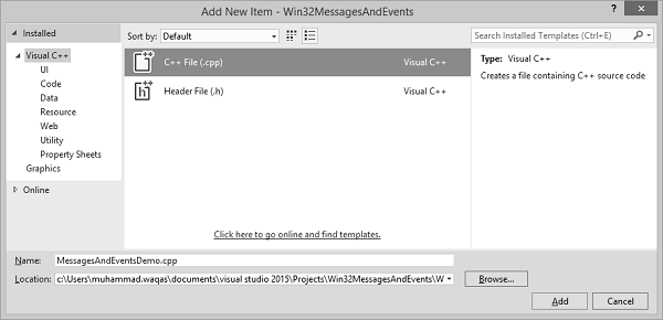
Step 7 − Click Add to Continue.
Step 8 − Now, add the following code in the *.cpp file.
#include <afxwin.h>
class CMainFrame : public CFrameWnd {
   public:
      CMainFrame();
   protected:
      DECLARE_MESSAGE_MAP()
};

CMainFrame::CMainFrame() {
   // Create the window's frame
   Create(NULL, L"MFC Messages Demo", WS_OVERLAPPEDWINDOW,
      CRect(120, 100, 700, 480), NULL);
}

class CMessagesApp : public CWinApp {
   public:
      BOOL InitInstance();
};

BEGIN_MESSAGE_MAP(CMainFrame, CFrameWnd)
END_MESSAGE_MAP()
BOOL CMessagesApp::InitInstance() {
   m_pMainWnd = new CMainFrame;
   m_pMainWnd->ShowWindow(SW_SHOW);
   m_pMainWnd->UpdateWindow();
   return TRUE;
}
CMessagesApp theApp;
Windows Messages
There are different types of Windows messages like creating a window, showing a window etc. Here are some of the commonly used windows messages.
Let us look into a simple example of window creation.
WM_CREATE − When an object, called a window, is created, the frame that creates the objects sends a message identified as ON_WM_CREATE.
Step 1 − To create ON_WM_CREATE, add afx_msg int OnCreate(LPCREATESTRUCT lpCreateStruct); before the DECLARE_MESSAGE_MAP() as shown below.
class CMainFrame : public CFrameWnd {
   public:
      CMainFrame();
   protected:
      afx_msg int OnCreate(LPCREATESTRUCT lpCreateStruct);
      DECLARE_MESSAGE_MAP()
};
Step 2 − Add the ON_WM_CREATE() after the BEGIN_MESSAGE_MAP(CMainFrame, CFrameWnd) and before END_MESSAGE_MAP()
BEGIN_MESSAGE_MAP(CMainFrame, CFrameWnd)
   ON_WM_CREATE()
END_MESSAGE_MAP()
Step 3 − Here is the Implementation of OnCreate()
int CMainFrame::OnCreate(LPCREATESTRUCT lpCreateStruct) {
   // Call the base class to create the window
   if (CFrameWnd::OnCreate(lpCreateStruct) == 0) {

      // If the window was successfully created, let the user know
      MessageBox(L"The window has been created!!!");
      // Since the window was successfully created, return 0
      return 0;
   }
   // Otherwise, return -1
   return -1;
}
Step 4 − Now your *.cpp file will look like as shown in the following code.
#include <afxwin.h>
class CMainFrame : public CFrameWnd {
   public:
      CMainFrame();
   protected:
      afx_msg int OnCreate(LPCREATESTRUCT lpCreateStruct);
      DECLARE_MESSAGE_MAP()
};
CMainFrame::CMainFrame() {

   // Create the window's frame
   Create(NULL, L"MFC Messages Demo", WS_OVERLAPPEDWINDOW,
      CRect(120, 100, 700, 480), NULL);
}
class CMessagesApp : public CWinApp {
   public:
      BOOL InitInstance();
};
BEGIN_MESSAGE_MAP(CMainFrame, CFrameWnd)
   ON_WM_CREATE()
END_MESSAGE_MAP()
int CMainFrame::OnCreate(LPCREATESTRUCT lpCreateStruct) {
   // Call the base class to create the window
   if (CFrameWnd::OnCreate(lpCreateStruct) == 0) {
      // If the window was successfully created, let the user know
      MessageBox(L"The window has been created!!!");
      // Since the window was successfully created, return 0
      return 0;
   }
   // Otherwise, return -1
   return -1;
}
BOOL CMessagesApp::InitInstance() {
   m_pMainWnd = new CMainFrame;
   m_pMainWnd -> ShowWindow(SW_SHOW);
   m_pMainWnd -> UpdateWindow();
   return TRUE;
}
CMessagesApp theApp;
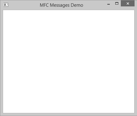
Step 5 − When the above code is compiled and executed, you will see the following output.
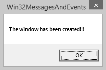
Step 6 − When you click OK, it will display the main window.
Command Messages
One of the main features of a graphical application is to present Windows controls and resources that allow the user to interact with the machine. Examples of controls that we will learn are buttons, list boxes, combo boxes, etc.
One type of resource we introduced in the previous lesson is the menu. Such controls and resources can initiate their own messages when the user clicks them. A message that emanates from a Windows control or a resource is called a command message.
Let us look into a simple example of Command messages.
To provide your application the ability to create a new document, the CWinApp class provides the OnFileNew() method.
afx_msg void OnFileNew();

BEGIN_MESSAGE_MAP(CMainFrame, CFrameWnd)
   ON_COMMAND(ID_FILE_NEW, CMainFrame::OnFileNew)
END_MESSAGE_MAP()
Here is the method definition −
void CMainFrame::OnFileNew() {
   // Create New file
}
Keyboard Messages
A keyboard is a hardware object attached to the computer. By default, it is used to enter recognizable symbols, letters, and other characters on a control. Each key on the keyboard displays a symbol, a letter, or a combination of those, to give an indication of what the key could be used for. The user typically presses a key, which sends a signal to a program.
Each key has a code that the operating system can recognize. This code is known as the virtual key code.
Pressing a key causes a WM_KEYDOWN or WM_SYSKEYDOWN message to be placed in the thread message. This can be defined as follows −
afx_msg void OnKeyDown(UINT nChar, UINT nRepCnt, UINT nFlags);
Let us look into a simple example.
Step 1 − Here is the message.
BEGIN_MESSAGE_MAP(CMainFrame, CFrameWnd)
   ON_WM_CREATE()
   ON_WM_KEYDOWN()
END_MESSAGE_MAP()
Step 2 − Here is the implementation of OnKeyDown().
void CMainFrame::OnKeyDown(UINT nChar, UINT nRepCnt, UINT nFlags) {
   switch (nChar) {

      case VK_RETURN:
         MessageBox(L"You pressed Enter");
         break;
      case VK_F1:
         MessageBox(L"Help is not available at the moment");
         break;
      case VK_DELETE:
         MessageBox(L"Can't Delete This");
         break;
      default:
         MessageBox(L"Whatever");
   }
}
Step 3 − When the above code is compiled and executed, you will see the following output.
Step 4 − When you press Enter, it will display the following message.
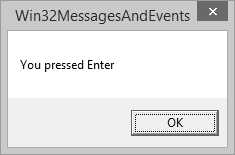
Mouse Messages
The mouse is another object that is attached to the computer allowing the user to interact with the machine.
If the left mouse button was pressed, an ON_WM_LBUTTONDOWN message is sent. The syntax of this message is −
afx_msg void OnLButtonDown(UINT nFlags, CPoint point)
If the right mouse button was pressed, an ON_WM_RBUTTONDOWN message is sent. Its syntax is −
afx_msg void OnRButtonDown(UINT nFlags, CPoint point)
Similarly If the left mouse is being released, the ON_WM_LBUTTONUP message is sent. Its syntax is −
afx_msg void OnLButtonUp(UINT nFlags, CPoint point)
If the right mouse is being released, the ON_WM_TBUTTONUP message is sent. Its syntax is −
afx_msg void OnRButtonUp(UINT nFlags, CPoint point)
Let us look into a simple example.
Step 1 − Add the following two functions in CMainFrame class definition as shown in the following code.
class CMainFrame : public CFrameWnd {
   public:
      CMainFrame();
   protected:
      afx_msg void OnKeyDown(UINT nChar, UINT nRepCnt, UINT nFlags);
      afx_msg void OnLButtonDown(UINT nFlags, CPoint point);
      afx_msg void OnRButtonUp(UINT nFlags, CPoint point);
      DECLARE_MESSAGE_MAP()
};
Step 2 − Add the following two Message Maps.
BEGIN_MESSAGE_MAP(CMainFrame, CFrameWnd)
   ON_WM_KEYDOWN()
   ON_WM_LBUTTONDOWN()
   ON_WM_RBUTTONUP()
END_MESSAGE_MAP()
Step 3 − Here is the functions definition.
void CMainFrame::OnLButtonDown(UINT nFlags, CPoint point) {
   CString MsgCoord;
   MsgCoord.Format(L"Left Button at P(%d, %d)", point.x, point.y);
   MessageBox(MsgCoord);
}
void CMainFrame::OnRButtonUp(UINT nFlags, CPoint point) {
   MessageBox(L"Right Mouse Button Up");
}
Step 4 − When you run this application, you will see the following output.
Step 5 − When you click OK, you will see the following message.
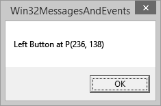
Step 6 − Right-click on this window. Now, when you release the right button of the mouse, it will display the following message.
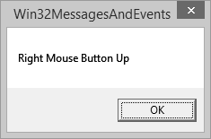
MFC - Activex Control
An ActiveX control container is a parent program that supplies the environment for an ActiveX (formerly OLE) control to run.
ActiveX control is a control using Microsoft ActiveX technologies.
ActiveX is not a programming language, but rather a set of rules for how applications should share information.
Programmers can develop ActiveX controls in a variety of languages, including C, C++, Visual Basic, and Java.
You can create an application capable of containing ActiveX controls with or without MFC, but it is much easier to do with MFC.
Let us look into simple example of add ActiveX controls in your MFC dialog based application.
Step 1 − Right-click on the dialog in the designer window and select Insert ActiveX Control.
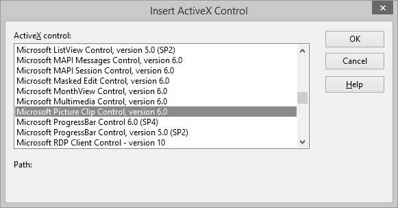
Step 2 − Select the Microsoft Picture Clip Control and click OK.
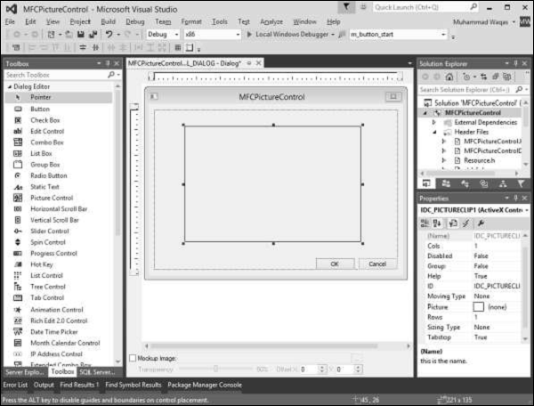
Step 3 − Resize the Picture control and in the Properties window, click the Picture field.
Step 4 − Browse the folder that contains Pictures. Select any picture.
Step 5 − When you run this application, you will see the following output.
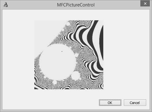
Let us have a look into another simple example.
Step 1 − Right-click on the dialog in the designer window.
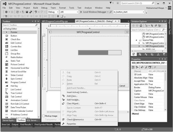
Step 2 − Select Insert ActiveX Control.
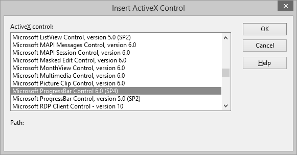
Step 3 − Select the Microsoft ProgressBar Control 6.0, click OK.
Step 4 − Select the progress bar and set its Orientation in the Properties Window to 1 – ccOrientationVertical.
Step 5 − Add control variable for Progress bar.
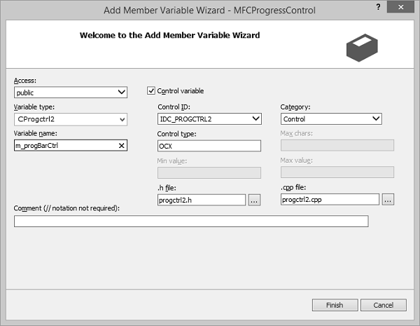
Step 6 − Add the following code in the OnInitDialog()
m_progBarCtrl.SetScrollRange(0,100,TRUE);
m_progBarCtrl.put_Value(53);
Step 7 − When you run this application again, you will see the progress bar in Vertical direction as well.
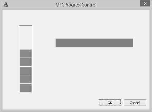
MFC - File System
In this chapter, we will discuss the various components of the file system.
Drives
A drive is a physical device attached to a computer so it can store information. A logical disk, logical volume or virtual disk (VD or vdisk for short) is a virtual device that provides an area of usable storage capacity on one or more physical disk drive(s) in a computer system. A drive can be a hard disk, a CD ROM, a DVD ROM, a flash (USB) drive, a memory card, etc.
One of the primary operations you will want to perform is to get a list of drives on the computer.
Let us look into a simple example by creating a new MFC dialog based application.
Step 1 − Drag one button from the toolbox, change its Caption to Get Drives Info.
Step 2 − Remove the Caption of Static control (TODO line) and change its ID to IDC_STATIC_TEXT.
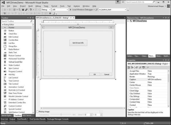
Step 3 − Right-click on the button and select Add Event Handler.
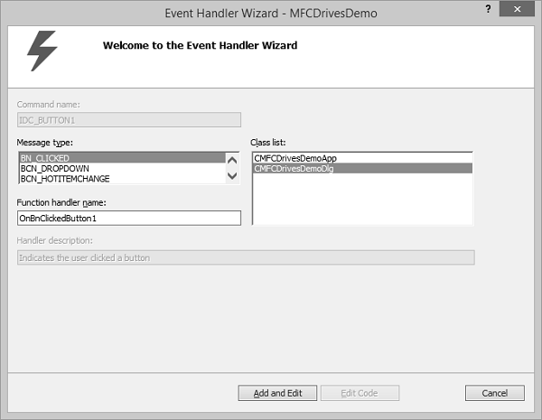
Step 4 − Select the BN_CLICKED message type and click the Add and Edit button.
Step 5 − Add the value variable m_strDrives for Static Text control.
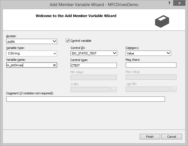
To support drives on a computer, the Win32 library provides the GetLogicalDrives() function of Microsoft Window, which will retrieve a list of all drives on the current computer.
Step 6 − When the above code is compiled and executed, you will see the following output.

Step 7 − When you click the button, you can see all the drives on your computer.
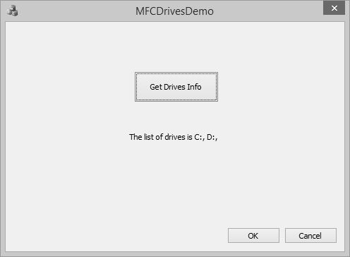
Directories
In computing, a directory is a file system cataloging structure which contains references to other computer files, and possibly other directories. Directory is a physical location. It can handle operations not available on a drive.
Let us look into a simple example by creating a new MFC dialog based application
Step 1 − Drag three buttons from the toolbox. Change their Captions to Create Directory, Delete Directory and Move Directory.
Step 2 − Change the IDs of these buttons to IDC_BUTTON_CREATE, IDC_BUTTON_DELETE and IDC_BUTTON_MOVE.
Step 3 − Remove the TODO line.
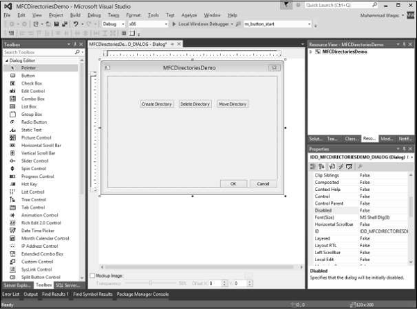
Step 4 − Add event handler for each button.
Step 5 − To create a directory, you can call the CreateDirectory() method of the Win32 library.
Step 6 − Here is the Create button event handler implementation in which we will create one directory and then two more sub directories.
void CMFCDirectoriesDemoDlg::OnBnClickedButtonCreate() {
   // TODO: Add your control notification handler code here
   SECURITY_ATTRIBUTES saPermissions;

   saPermissions.nLength = sizeof(SECURITY_ATTRIBUTES);
   saPermissions.lpSecurityDescriptor = NULL;
   saPermissions.bInheritHandle = TRUE;

   if (CreateDirectory(L"D:\\MFCDirectoryDEMO", &saPermissions) == TRUE)
      AfxMessageBox(L"The directory was created.");
   CreateDirectory(L"D:\\MFCDirectoryDEMO\\Dir1", NULL);
   CreateDirectory(L"D:\\MFCDirectoryDEMO\\Dir2", NULL);
}
Step 7 − To get rid of a directory, you can call the RemoveDirectory() function of the Win32 library. Here is the implementation of delete button event handler.
void CMFCDirectoriesDemoDlg::OnBnClickedButtonDelete() {
   // TODO: Add your control notification handler code here
   if (RemoveDirectory(L"D:\\MFCDirectoryDEMO\\Dir1") == TRUE)
      AfxMessageBox(L"The directory has been deleted");
}
Step 8 − If you want to move a directory, you can also call the same MoveFile() function. Here is the implementation of move button event handler in which we will create first new directory and then move the Dir2 to that directory.
void CMFCDirectoriesDemoDlg::OnBnClickedButtonMove() {
   // TODO: Add your control notification handler code here
   CreateDirectory(L"D:\\MFCDirectory", NULL);

   if (MoveFile(L"D:\\MFCDirectoryDEMO\\Dir1", L"D:\\MFCDirectory\\Dir1") == TRUE)
      AfxMessageBox(L"The directory has been moved");
}
Step 9 − When the above code is compiled and executed, you will see the following output.
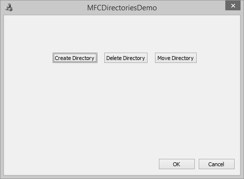
Step 10 − When you click the Create Directory button, it will create these directories.
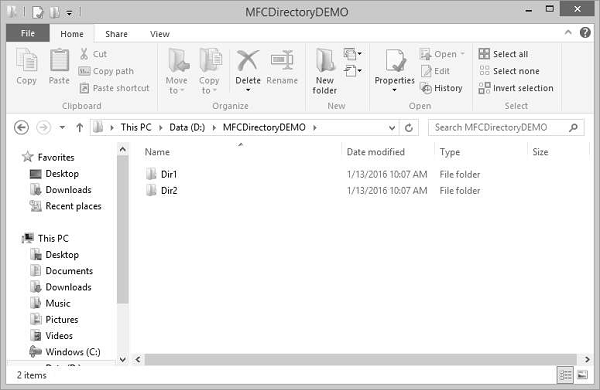
Step 11 − When you click on Delete Directory button, it will delete the Dir1.
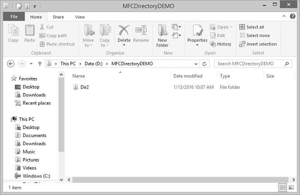
File Processing
Most of the file processing in an MFC application is performed in conjunction with a class named CArchive. The CArchive class serves as a relay between the application and the medium used to either store data or make it available. It allows you to save a complex network of objects in a permanent binary form (usually disk storage) that persists after those objects are deleted.
Here is the list of methods in CArchive class −
Here is the list of operators used to store and retrieve data
| Sr.No. | Name & Description |
|---|---|
| 1 | operator << Stores objects and primitive types to the archive. |
| 2 | operator >> Loads objects and primitive types from the archive. |
Let us look into a simple example by creating a new MFC dialog based application.
Step 1 − Drag one edit control and two buttons as shown in the following snapshot.
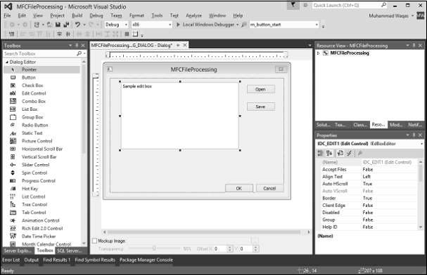
Step 2 − Add control variable m_editCtrl and value variable m_strEdit for edit control.
Step 3 − Add click event handler for Open and Save buttons.
Step 4 − Here is the implementation of event handlers.
void CMFCFileProcessingDlg::OnBnClickedButtonOpen() {
   // TODO: Add your control notification handler code here
   UpdateData(TRUE);

   CFile file;

   file.Open(L"ArchiveText.rpr", CFile::modeRead);
   if(file) {
      CArchive ar(&file, CArchive::load);

      ar >> m_strEdit;

      ar.Close();
      file.Close();
   }
   UpdateData(FALSE);
}

void CMFCFileProcessingDlg::OnBnClickedButtonSave() {
   // TODO: Add your control notification handler code here
   UpdateData(TRUE);

   if (m_strEdit.GetLength() == 0) {
      AfxMessageBox(L"You must enter the name of the text.");
      return;
   }
   CFile file;

   file.Open(L"ArchiveText.rpr", CFile::modeCreate | CFile::modeWrite);
   CArchive ar(&file, CArchive::store);
   ar << m_strEdit;

   ar.Close();
   file.Close();
}
Step 5 − When the above code is compiled and executed, you will see the following output.
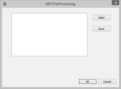
Step 6 − Write something and click Save. It will save the data in binary format.
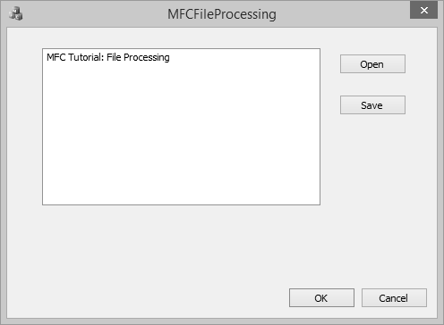
Step 7 − Remove the test from edit control. As you click Open, observe that the same text is loaded again.
MFC - Standard I/O
The MFC library provides its own version of file processing. This is done through a class named CStdioFile. The CStdioFile class is derived from CFile. It can handle the reading and writing of Unicode text files as well as ordinary multi-byte text files.
Here is the list of constructors, which can initialize a CStdioFile object −
CStdioFile();
CStdioFile(CAtlTransactionManager* pTM);
CStdioFile(FILE* pOpenStream);
CStdioFile(LPCTSTR lpszFileName, UINT nOpenFlags);
CStdioFile(LPCTSTR lpszFileName, UINT nOpenFlags, CAtlTransactionManager* pTM);
Here is the list of methods in CStdioFile −
| Sr.No. | Name & Description |
|---|---|
| 1 | Open Overloaded. Open is designed for use with the default CStdioFile constructor (Overrides CFile::Open). |
| 2 | ReadString Reads a single line of text. |
| 3 | Seek Positions the current file pointer. |
| 4 | WriteString Writes a single line of text. |
Let us look into a simple example again by creating a new MFC dialog based application.
Step 1 − Drag one edit control and two buttons as shown in the following snapshot.
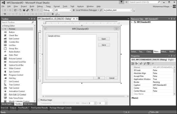
Step 2 − Add value variable m_strEditCtrl for edit control.

Step 3 − Add click event handler for Open and Save buttons.
Step 4 − Here is the implementation of event handlers.
void CMFCStandardIODlg::OnBnClickedButtonOpen() {

   // TODO: Add your control notification handler code here
   UpdateData(TRUE);

   CStdioFile file;
   file.Open(L"D:\\MFCDirectoryDEMO\\test.txt", CFile::modeRead | CFile::typeText);

   file.ReadString(m_strEditCtrl);
   file.Close();
   UpdateData(FALSE);
}

void CMFCStandardIODlg::OnBnClickedButtonSave() {

   // TODO: Add your control notification handler code here
   UpdateData(TRUE);
   CStdioFile file;
   if (m_strEditCtrl.GetLength() == 0) {

      AfxMessageBox(L"You must specify the text.");
      return;
   }
   file.Open(L"D:\\MFCDirectoryDEMO\\test.txt", CFile::modeCreate |
      CFile::modeWrite | CFile::typeText);
   file.WriteString(m_strEditCtrl);
   file.Close();
}
Step 5 − When the above code is compiled and executed, you will see the following output.
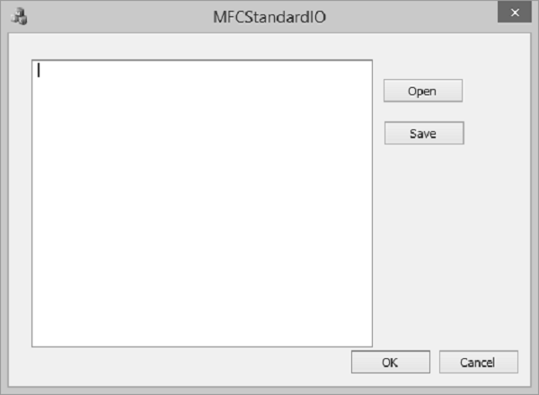
Step 6 − Write something and click Save. It will save the data in *.txt file.
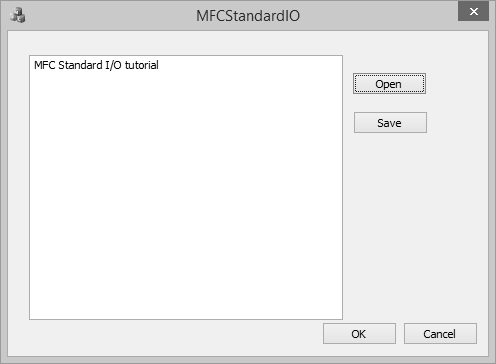
Step 7 − If you look at the location of the file, you will see that it contains the test.txt file.
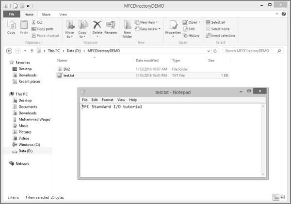
Step 8 − Now, close the application. Run the same application. When you click Open, the same text loads again.
Step 9 − It starts by opening the file, reading the file, followed by updating the Edit Control.
MFC - Document View
The Document/View architecture is the foundation used to create applications based on the Microsoft Foundation Classes library. It allows you to make distinct the different parts that compose a computer program including what the user sees as part of your application and the document a user would work on. This is done through a combination of separate classes that work as an ensemble.
The parts that compose the Document/View architecture are a frame, one or more documents, and the view. Put together, these entities make up a usable application.
View
A view is the platform the user is working on to do his or her job. To let the user do anything on an application, you must provide a view, which is an object based on the CView class. You can either directly use one of the classes derivedfrom CView or you can derive your own custom class from CView or one of its child classes.
Document
A document is similar to a bucket. For a computer application, a document holds the user's data. To create the document part of this architecture, you must derive an object from the CDocument class.
Frame
As the name suggests, a frame is a combination of the building blocks, the structure, and the borders of an item. A frame gives "physical" presence to a window. It also defines the location of an object with regards to the Windows desktop.
Single Document Interface (SDI)
The expression Single Document Interface or SDI refers to a document that can present only one view to the user. This means that the application cannot display more than one document at a time. If you want to view another type of document of the current application, you must create another instance of the application. Notepad and WordPad are examples of SDI applications.
Let us look into a simple example of single document interface or SDI by creating a new MFC dialog based application.
Step 1 − Let us create a new MFC Application MFCSDIDemo with below mentioned settings.
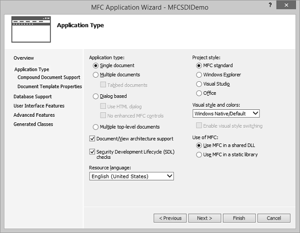
Step 2 − Select Single document from the Application type and MFC standard from Project Style.
Step 3 − Click Finish to Continue.
Step 4 − Once the project is created, run the application and you will see the following output.
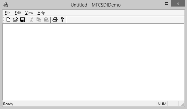
Multiple Document Interface (MDI)
An application is referred to as a Multiple Document Interface, or MDI, if the user can open more than one document in the application without closing it. To provide this functionality, the application provides a parent frame that acts as the main frame of the computer program. Inside this frame, the application allows creating views with individual frames, making each view distinct from the other.
Let us look into a simple example of multiple document interface or MDI by creating a new MFC dialog based application.
Step 1 − Let us create a new MFC Application MFCMDIDemo with below mentioned settings.
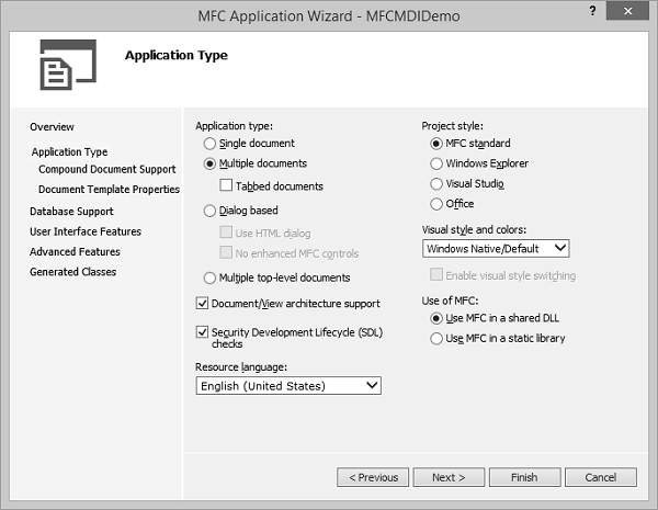
Step 2 − Select Multiple document from the Application type and MFC standard from Project Style.
Step 3 − Click Finish to Continue.
Step 4 − Once the project is created, run the application and you will see the following output.
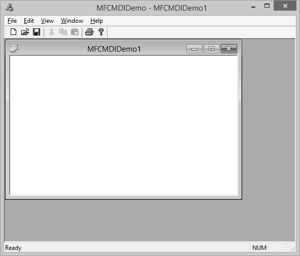
Step 5 − When you click on File → New menu option, it will create another child window as shown in the following snapshot.
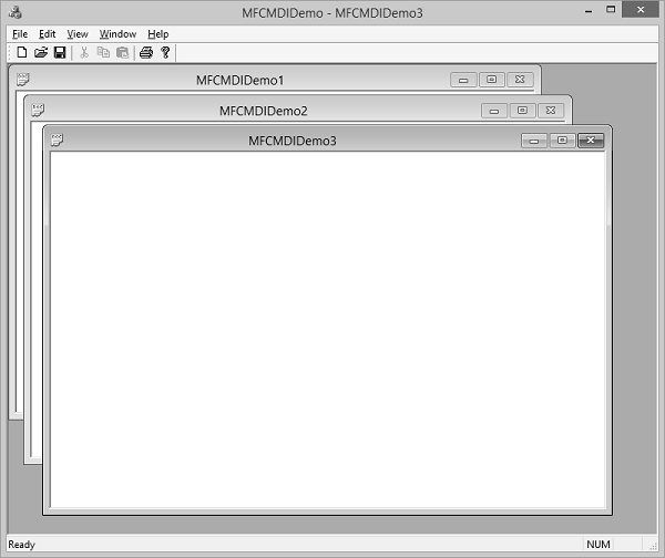
Step 6 − In Multiple Document Interface (MDI) applications, there is one main frame per application. In this case, a CMDIFrameWnd, and one CMDIChildWnd derived child frame for each document.
MFC - Strings
Strings are objects that represent sequences of characters. The C-style character string originated within the C language and continues to be supported within C++.
This string is actually a one-dimensional array of characters which is terminated by a null character '\0'.
A null-terminated string contains the characters that comprise the string followed by a null.
Here is the simple example of character array.
char word[12] = { 'H', 'e', 'l', 'l', 'o', ' ', 'W', 'o', 'r', 'l', 'd', '\0' };
Following is another way to represent it.
char word[] = "Hello, World";
Microsoft Foundation Class (MFC) library provides a class to manipulate string called CString. Following are some important features of CString.
CString does not have a base class.
A CString object consists of a variable-length sequence of characters.
CString provides functions and operators using a syntax similar to that of Basic.
Concatenation and comparison operators, together with simplified memory management, make CString objects easier to use than ordinary character arrays.
Here is the constructor of CString.
| Sr.No. | Method & Description |
|---|---|
| 1 | CString Constructs CString objects in various ways |
Here is a list of Array Methods −
| Sr.No. | Method & Description |
|---|---|
| 1 | GetLength Returns the number of characters in a CString object. |
| 2 | IsEmpty Tests whether a CString object contains no characters. |
| 3 | Empty Forces a string to have 0 length. |
| 4 | GetAt Returns the character at a specified position. |
| 5 | SetAt Sets a character at a specified position. |
Here is a list of Comparison Methods −
| Sr.No. | Method & Description |
|---|---|
| 1 | Compare Compares two strings (case sensitive). |
| 2 | CompareNoCase Compares two strings (case insensitive). |
Here is a list of Extraction Methods −
| Sr.No. | Method & Description |
|---|---|
| 1 | Mid Extracts the middle part of a string (like the Basic MID$ function). |
| 2 | Left Extracts the left part of a string (like the Basic LEFT$ function). |
| 3 | Right Extracts the right part of a string (like the Basic RIGHT$ function). |
| 4 | SpanIncluding Extracts the characters from the string, which are in the given character set. |
| 5 | SpanExcluding Extracts the characters from the string which are not in the given character set. |
Here is a list of Conversion Methods.
| Sr.No. | Method & Description |
|---|---|
| 1 | MakeUpper Converts all the characters in this string to uppercase characters. |
| 2 | MakeLower Converts all the characters in this string to lowercase characters. |
| 3 | MakeReverse Reverses the characters in this string. |
| 4 | Format Format the string as sprintf does. |
| 5 | TrimLeft Trim leading white-space characters from the string. |
| 6 | TrimRight Trim trailing white-space characters from the string. |
Here is a list of Searching Methods.
| Sr.No. | Method & Description |
|---|---|
| 1 | Find Finds a character or substring inside a larger string. |
| 2 | ReverseFind Finds a character inside a larger string; starts from the end. |
| 3 | FindOneOf Finds the first matching character from a set. |
Here is a list of Buffer Access Methods.
| Sr.No. | Method & Description |
|---|---|
| 1 | GetBuffer Returns a pointer to the characters in the CString. |
| 2 | GetBufferSetLength Returns a pointer to the characters in the CString, truncating to the specified length. |
| 3 | ReleaseBuffer Releases control of the buffer returned by GetBuffer |
| 4 | FreeExtra Removes any overhead of this string object by freeing any extra memory previously allocated to the string. |
| 5 | LockBuffer Disables reference counting and protects the string in the buffer. |
| 6 | UnlockBuffer Enables reference counting and releases the string in the buffer. |
Here is a list of Windows-Specific Methods.
| Sr.No. | Method & Description |
|---|---|
| 1 | AllocSysString Allocates a BSTR from CString data. |
| 2 | SetSysString Sets an existing BSTR object with data from a CString object. |
| 3 | LoadString Loads an existing CString object from a Windows CE resource. |
Following are the different operations on CString objects −
Create String
You can create a string by either using a string literal or creating an instance of CString class.
BOOL CMFCStringDemoDlg::OnInitDialog() {

   CDialogEx::OnInitDialog();

   // Set the icon for this dialog. The framework does this automatically
   // when the application's main window is not a dialog
   SetIcon(m_hIcon, TRUE);         // Set big icon
   SetIcon(m_hIcon, FALSE);       // Set small icon

   CString string1 = _T("This is a string1");
   CString string2("This is a string2");

   m_strText.Append(string1 + L"\n");
   m_strText.Append(string2);

   UpdateData(FALSE);

   return TRUE; // return TRUE unless you set the focus to a control
}
When the above code is compiled and executed, you will see the following output.
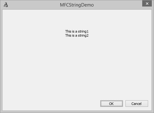
Empty String
You can create an empty string by either using an empty string literal or by using CString::Empty() method. You can also check whether a string is empty or not using Boolean property isEmpty.
BOOL CMFCStringDemoDlg::OnInitDialog() {
   CDialogEx::OnInitDialog();

   // Set the icon for this dialog. The framework does this automatically
   // when the application's main window is not a dialog
   SetIcon(m_hIcon, TRUE);            // Set big icon
   SetIcon(m_hIcon, FALSE);           // Set small icon

   CString string1 = _T("");
   CString string2;
   string2.Empty();

   if(string1.IsEmpty())
      m_strText.Append(L"String1 is empty\n");
   else
      m_strText.Append(string1 + L"\n");

   if(string2.IsEmpty())
      m_strText.Append(L"String2 is empty");
   else
      m_strText.Append(string2);
   UpdateData(FALSE);
   return TRUE; // return TRUE unless you set the focus to a control
}
When the above code is compiled and executed you will see the following output.
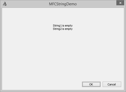
String Concatenation
To concatenate two or more strings, you can use + operator to concatenate two strings or a CString::Append() method.
BOOL CMFCStringDemoDlg::OnInitDialog() {
   CDialogEx::OnInitDialog();

   // Set the icon for this dialog. The framework does this automatically
   // when the application's main window is not a dialog
   SetIcon(m_hIcon, TRUE);              // Set big icon
   SetIcon(m_hIcon, FALSE);              // Set small icon

   //To concatenate two CString objects
   CString s1 = _T("This ");           // Cascading concatenation
   s1 += _T("is a ");
   CString s2 = _T("test");
   CString message = s1;
   message.Append(_T("big ") + s2);
   // Message contains "This is a big test".

   m_strText = L"message: " + message;

   UpdateData(FALSE);

   return TRUE; // return TRUE unless you set the focus to a control
}
When the above code is compiled and executed you will see the following output.
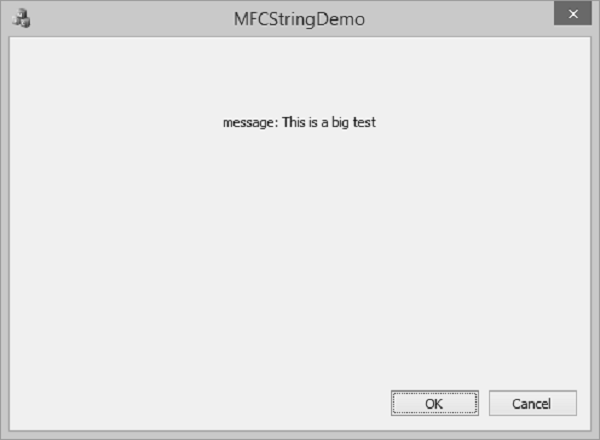
String Length
To find the length of the string you can use the CString::GetLength() method, which returns the number of characters in a CString object.
BOOL CMFCStringDemoDlg::OnInitDialog() {
   CDialogEx::OnInitDialog();

   // Set the icon for this dialog. The framework does this automatically
   // when the application's main window is not a dialog
   SetIcon(m_hIcon, TRUE);              // Set big icon
   SetIcon(m_hIcon, FALSE);              // Set small icon

   CString string1 = _T("This is string 1");
   int length = string1.GetLength();
   CString strLen;

   strLen.Format(L"\nString1 contains %d characters", length);
   m_strText = string1 + strLen;

   UpdateData(FALSE);

   return TRUE; // return TRUE unless you set the focus to a control
}
When the above code is compiled and executed you will see the following output.
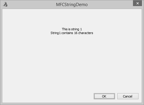
String Comparison
To compare two strings variables you can use == operator
BOOL CMFCStringDemoDlg::OnInitDialog() {
   CDialogEx::OnInitDialog();

   // Set the icon for this dialog. The framework does this automatically
   // when the application's main window is not a dialog
   SetIcon(m_hIcon, TRUE);            // Set big icon
   SetIcon(m_hIcon, FALSE);          // Set small icon

   CString string1 = _T("Hello");
   CString string2 = _T("World");

   CString string3 = _T("MFC Tutorial");
   CString string4 = _T("MFC Tutorial");

   if (string1 == string2)
      m_strText = "string1 and string1 are same\n";
   else
      m_strText = "string1 and string1 are not same\n";

   if (string3 == string4)
      m_strText += "string3 and string4 are same";
   else
      m_strText += "string3 and string4 are not same";

   UpdateData(FALSE);

   return TRUE; // return TRUE unless you set the focus to a control
}
When the above code is compiled and executed you will see the following output.
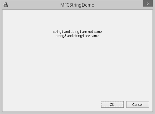
MFC - CArray
CArray is a collection that is best used for data that is to be accessed in a random or non sequential manner. CArray class supports arrays that are like C arrays, but can dynamically shrink and grow as necessary.
Array indexes always start at position 0.
You can decide whether to fix the upper bound or enable the array to expand when you add elements past the current bound.
Memory is allocated contiguously to the upper bound, even if some elements are null.
Following are the different operations on CArray objects −
Create CArray Object
To create a collection of CArray values or objects, you must first decide the type of values of the collection. You can use one of the existing primitive data types such as int, CString, double etc. as shown below;
CArray<CString, CString>strArray;
Add items
To add an item you can use CArray::Add() function. It adds an item at the end of the array. In the OnInitDialog(), CArray object is created and three names are added as shown in the following code.
CArray<CString, CString>strArray;

//Add names to CArray
strArray.Add(L"Ali");
strArray.Add(L"Ahmed");
strArray.Add(L"Mark");
Retrieve Items
To retrieve any item, you can use the CArray::GetAt() function. This function takes one integer parameter as an index of the array.
Step 1 − Let us look at a simple example, which will retrieve all the names.
//Retrive names from CArray
   for (int i = 0; i < strArray.GetSize(); i++) {
      m_strText.Append(strArray.GetAt(i) + L"\n");
   }
Step 2 − Here is the complete implementation of CMFCCArrayDlg::OnInitDialog()
BOOL CMFCCArrayDlg::OnInitDialog() {
   CDialogEx::OnInitDialog();

   // Set the icon for this dialog. The framework does this automatically
   // when the application's main window is not a dialog
   SetIcon(m_hIcon, TRUE);               // Set big icon
   SetIcon(m_hIcon, FALSE);             // Set small icon

   // TODO: Add extra initialization here
   CArray<CString, CString>strArray;

   //Add names to CArray
   strArray.Add(L"Ali");
   strArray.Add(L"Ahmed");
   strArray.Add(L"Mark");

   //Retrive names from CArray
   for (int i = 0; i < strArray.GetSize(); i++) {
      m_strText.Append(strArray.GetAt(i) + L"\n");
   }

   UpdateData(FALSE);
   return TRUE; // return TRUE unless you set the focus to a control
}
Step 3 − When the above code is compiled and executed, you will see the following output.

Add Items in the Middle
To add item in the middle of array you can use the CArray::.InsertAt() function. It takes two paramerters — First, the index and Second, the value.
Let us insert a new item at index 1 as shown in the following code.
BOOL CMFCCArrayDlg::OnInitDialog() {

   CDialogEx::OnInitDialog();

   // Set the icon for this dialog. The framework does this automatically
   // when the application's main window is not a dialog
   SetIcon(m_hIcon, TRUE);             // Set big icon
   SetIcon(m_hIcon, FALSE);            // Set small icon

   // TODO: Add extra initialization here
   CArray<CString, CString>strArray;
   //Add names to CArray
   strArray.Add(L"Ali");
   strArray.Add(L"Ahmed");
   strArray.Add(L"Mark");

   strArray.InsertAt(1, L"Allan");

   //Retrive names from CArray
   for (int i = 0; i < strArray.GetSize(); i++) {
      m_strText.Append(strArray.GetAt(i) + L"\n");
   }

   UpdateData(FALSE);
   return TRUE; // return TRUE unless you set the focus to a control
}
When the above code is compiled and executed, you will see the following output. You can now see the name Allan dded as the second index.

Update Item Value
To update item in the middle of array you can use the CArray::.SetAt() function. It takes two paramerters — First, the index and Second, the value.
Let us update the third element in the array as shown in the following code.
BOOL CMFCCArrayDlg::OnInitDialog() {
   CDialogEx::OnInitDialog();

   // Set the icon for this dialog. The framework does this automatically
   // when the application's main window is not a dialog
   SetIcon(m_hIcon, TRUE);                 // Set big icon
   SetIcon(m_hIcon, FALSE);               // Set small icon

   // TODO: Add extra initialization here
   CArray<CString, CString>strArray;

   //Add names to CArray
   strArray.Add(L"Ali");
   strArray.Add(L"Ahmed");
   strArray.Add(L"Mark");

   strArray.InsertAt(1, L"Allan");

   strArray.SetAt(2, L"Salman");

   //Retrive names from CArray
   for (int i = 0; i < strArray.GetSize(); i++) {
      m_strText.Append(strArray.GetAt(i) + L"\n");
   }

   UpdateData(FALSE);
   return TRUE; // return TRUE unless you set the focus to a control
}
When the above code is compiled and executed, you will see the following output. You can now see that the value of third element is updated.
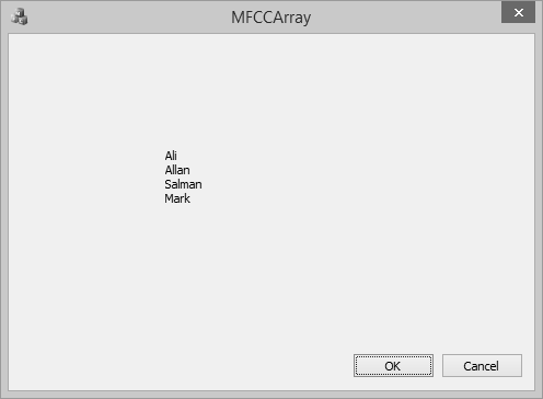
Copy Array
To copy the entire array into another CArray object, you can use CArray::Copy() function.
Step1 − Let us create another array and copy all the elements from first array as shown in the following code.
BOOL CMFCCArrayDlg::OnInitDialog() {
   CDialogEx::OnInitDialog();

   // Add "About..." menu item to system menu.

   // IDM_ABOUTBOX must be in the system command range.
   ASSERT((IDM_ABOUTBOX & 0xFFF0) == IDM_ABOUTBOX);
   ASSERT(IDM_ABOUTBOX < 0xF000);
   CMenu* pSysMenu = GetSystemMenu(FALSE);
   if (pSysMenu != NULL) {
      BOOL bNameValid;
      CString strAboutMenu;
      bNameValid = strAboutMenu.LoadString(IDS_ABOUTBOX);
      ASSERT(bNameValid);
      if (!strAboutMenu.IsEmpty()) {
         pSysMenu→AppendMenu(MF_SEPARATOR);
         pSysMenu→AppendMenu(MF_STRING, IDM_ABOUTBOX, strAboutMenu);
      }
   }
   // Set the icon for this dialog. The framework does this automatically
   // when the application's main window is not a dialog
   SetIcon(m_hIcon, TRUE);               // Set big icon
   SetIcon(m_hIcon, FALSE);              // Set small icon

   // TODO: Add extra initialization here
   CArray<CString, CString>strArray;
   //Add names to CArray
   strArray.Add(L"Ali");
   strArray.Add(L"Ahmed");
   strArray.Add(L"Mark");

   strArray.InsertAt(1, L"Allan");

   strArray.SetAt(2, L"Salman");

   CArray<CString, CString>strArray2;
   strArray2.Copy(strArray);
   //Retrive names from CArray
   for (int i = 0; i < strArray2.GetSize(); i++) {
      m_strText.Append(strArray2.GetAt(i) + L"\n");
   }

   UpdateData(FALSE);
   return TRUE; // return TRUE unless you set the focus to a control
}
You can now see that we have retrieved element from the 2nd array and the output is the same because we have used the copy function.

Remove Items
To remove any particular item, you can use CArray::RemoveAt() function. To remove all the element from the list, CArray::RemoveAll() function can be used.
Let us remove the second element from an array.
BOOL CMFCCArrayDlg::OnInitDialog() {
   CDialogEx::OnInitDialog();

   SetIcon(m_hIcon, TRUE);             // Set big icon
   SetIcon(m_hIcon, FALSE);            // Set small icon

   // TODO: Add extra initialization here
   CArray<CString, CString>strArray;

   //Add names to CArray
   strArray.Add(L"Ali");
   strArray.Add(L"Ahmed");
   strArray.Add(L"Mark");

   strArray.InsertAt(1, L"Allan");

   strArray.SetAt(2, L"Salman");

   CArray<CString, CString>strArray2;
   strArray2.Copy(strArray);

   strArray2.RemoveAt(1);

   //Retrive names from CArray
   for (int i = 0; i < strArray2.GetSize(); i++) {
      m_strText.Append(strArray2.GetAt(i) + L"\n");
   }

   UpdateData(FALSE);
   return TRUE; // return TRUE unless you set the focus to a control
}
When the above code is compiled and executed, you will see the following output. You can now see that the name Allan is no longer part of the array.
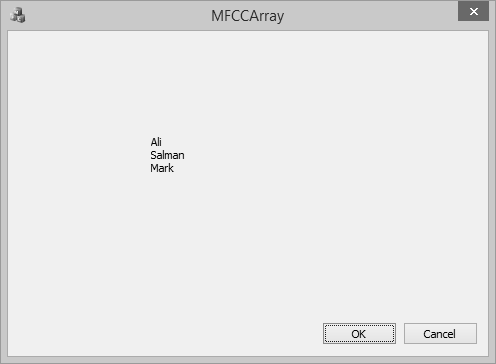
MFC - Linked Lists
A linked list is a linear data structure where each element is a separate object. Each element (we will call it a node) of a list comprises two items — the data and a reference to the next node. The last node has a reference to null.
A linked list is a data structure consisting of a group of nodes which together represent a sequence. It is a way to store data with structures so that the programmer can automatically create a new place to store data whenever necessary. Some of its salient features are −
Linked List is a sequence of links which contains items.
Each link contains a connection to another link.
Each item in the list is called a node.
If the list contains at least one node, then a new node is positioned as the last element in the list.
If the list has only one node, that node represents the first and the last item.
There are two types of link list −
Singly Linked List
Singly Linked Lists are a type of data structure. In a singly linked list, each node in the list stores the contents of the node and a pointer or reference to the next node in the list.
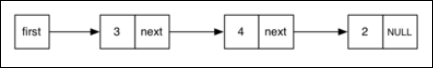
Doubly Linked List
A doubly linked list is a linked data structure that consists of a set of sequentially linked records called nodes. Each node contains two fields that are references to the previous and to the next node in the sequence of nodes.
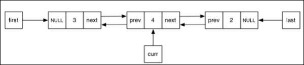
CList Class
MFC provides a class CList which is a template linked list implementation and works perfectly. CList lists behave like doubly-linked lists. A variable of type POSITION is a key for the list. You can use a POSITION variable as an iterator to traverse a list sequentially and as a bookmark to hold a place.
Following are the different operations on CList objects −
Create CList Object
To create a collection of CList values or objects, you must first decide the type of values of the collection. You can use one of the existing primitive data types such as int, CString, double etc. as shown below in the following code.
CList<double, double>m_list;
Add items
To add an item, you can use CList::AddTail() function. It adds an item at the end of the list. To add an element at the start of the list, you can use the CList::AddHead() function. In the OnInitDialog() CList, object is created and four values are added as shown in the following code.
CList<double, double>m_list;

//Add items to the list
m_list.AddTail(100.75);
m_list.AddTail(85.26);
m_list.AddTail(95.78);
m_list.AddTail(90.1);
Retrieve Items
A variable of type POSITION is a key for the list. You can use a POSITION variable as an iterator to traverse a list sequentially.
Step 1 − To retrieve the element from the list, we can use the following code which will retrieve all the values.
//iterate the list
POSITION pos = m_list.GetHeadPosition();
while (pos) {
   double nData = m_list.GetNext(pos);
   CString strVal;
   strVal.Format(L"%.2f\n", nData);
   m_strText.Append(strVal);
}
Step 2 − Here is the complete CMFCCListDemoDlg::OnInitDialog() function.
BOOL CMFCCListDemoDlg::OnInitDialog() {
   CDialogEx::OnInitDialog();

   // Set the icon for this dialog. The framework does this automatically
   // when the application's main window is not a dialog
   SetIcon(m_hIcon, TRUE);             // Set big icon
   SetIcon(m_hIcon, FALSE);             // Set small icon

   // TODO: Add extra initialization here
   CList<double, double>m_list;

   //Add items to the list
   m_list.AddTail(100.75);
   m_list.AddTail(85.26);
   m_list.AddTail(95.78);
   m_list.AddTail(90.1);

   //iterate the list
   POSITION pos = m_list.GetHeadPosition();
   while (pos) {
      double nData = m_list.GetNext(pos);
      CString strVal;
      strVal.Format(L"%.f\n", nData);
      m_strText.Append(strVal);
   }

   UpdateData(FALSE);

   return TRUE; // return TRUE unless you set the focus to a control
}
Step 3 − When the above code is compiled and executed, you will see the following output.
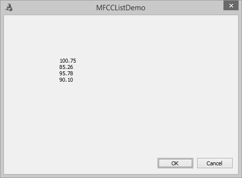
Add Items in the Middle
To add item in the middle of the list, you can use the CList::.InsertAfter() and CList::.InsertBefore() functions. It takes two paramerters — First, the position (where it can be added) and Second, the value.
Step 1 − Let us insert a new item as shown in the followng code.
BOOL CMFCCListDemoDlg::OnInitDialog() {
   CDialogEx::OnInitDialog();

   // Set the icon for this dialog. The framework does this automatically
   // when the application's main window is not a dialog
   SetIcon(m_hIcon, TRUE);             // Set big icon
   SetIcon(m_hIcon, FALSE);          // Set small icon

   // TODO: Add extra initialization here
   CList<double, double>m_list;

   //Add items to the list
   m_list.AddTail(100.75);
   m_list.AddTail(85.26);
   m_list.AddTail(95.78);
   m_list.AddTail(90.1);

   POSITION position = m_list.Find(85.26);
   m_list.InsertBefore(position, 200.0);
   m_list.InsertAfter(position, 300.0);

   //iterate the list
   POSITION pos = m_list.GetHeadPosition();
   while (pos) {
      double nData = m_list.GetNext(pos);
      CString strVal;
      strVal.Format(L"%.2f\n", nData);
      m_strText.Append(strVal);
   }

   UpdateData(FALSE);

   return TRUE; // return TRUE unless you set the focus to a control
}
Step 2 − You can now see see that we first retrieved the position of value 85.26 and then inserted one element before and one element after that value.
Step 3 − When the above code is compiled and executed, you will see the following output.
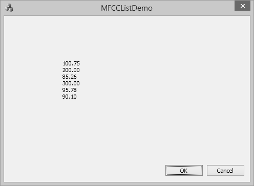
Update Item Value
To update item at the middle of array, you can use the CArray::.SetAt() function. It takes two paramerters — First, the position and Second, the value.
Let us update the 300.00 to 400 in the list as shown in the following code.
BOOL CMFCCListDemoDlg::OnInitDialog() {
   CDialogEx::OnInitDialog();

   // Set the icon for this dialog. The framework does this automatically
   // when the application's main window is not a dialog
   SetIcon(m_hIcon, TRUE);              // Set big icon
   SetIcon(m_hIcon, FALSE);            // Set small icon

   // TODO: Add extra initialization here
   CList<double, double>m_list;

   //Add items to the list
   m_list.AddTail(100.75);
   m_list.AddTail(85.26);
   m_list.AddTail(95.78);
   m_list.AddTail(90.1);

   POSITION position = m_list.Find(85.26);
   m_list.InsertBefore(position, 200.0);
   m_list.InsertAfter(position, 300.0);

   position = m_list.Find(300.00);
   m_list.SetAt(position, 400.00);

   //iterate the list
   POSITION pos = m_list.GetHeadPosition();
   while (pos) {
      double nData = m_list.GetNext(pos);
      CString strVal;
      strVal.Format(L"%.2f\n", nData);
      m_strText.Append(strVal);
   }

   UpdateData(FALSE);

   return TRUE; // return TRUE unless you set the focus to a control
}
When the above code is compiled and executed, you will see the following output. You can now see that the value of 300.00 is updated to 400.00.

Remove Items
To remove any particular item, you can use CList::RemoveAt() function. To remove all the element from the list, CList::RemoveAll() function can be used.
Let us remove the element, which has 95.78 as its value.
BOOL CMFCCListDemoDlg::OnInitDialog() {
   CDialogEx::OnInitDialog();

   // Set the icon for this dialog. The framework does this automatically
   // when the application's main window is not a dialog
   SetIcon(m_hIcon, TRUE);              // Set big icon
   SetIcon(m_hIcon, FALSE);             // Set small icon

   // TODO: Add extra initialization here
   CList<double, double>m_list;

   //Add items to the list
   m_list.AddTail(100.75);
   m_list.AddTail(85.26);
   m_list.AddTail(95.78);
   m_list.AddTail(90.1);

   POSITION position = m_list.Find(85.26);
   m_list.InsertBefore(position, 200.0);
   m_list.InsertAfter(position, 300.0);

   position = m_list.Find(300.00);
   m_list.SetAt(position, 400.00);

   position = m_list.Find(95.78);
   m_list.RemoveAt(position);

   //iterate the list
   POSITION pos = m_list.GetHeadPosition();
   while (pos) {
      double nData = m_list.GetNext(pos);
      CString strVal;
      strVal.Format(L"%.2f\n", nData);
      m_strText.Append(strVal);
   }
   UpdateData(FALSE);

   return TRUE; // return TRUE unless you set the focus to a control
}
When the above code is compiled and executed, you will see the following output. You can now see that the value of 95.78 is no longer part of the list.
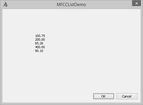
MFC - Database Classes
A database is a collection of information that is organized so that it can easily be accessed, managed, and updated. The MFC database classes based on ODBC are designed to provide access to any database for which an ODBC driver is available. Because the classes use ODBC, your application can access data in many different data formats and different local/remote configurations.
You do not have to write special-case code to handle different database management systems (DBMSs). As long as your users have an appropriate ODBC driver for the data they want to access, they can use your program to manipulate data in tables stored there. A data source is a specific instance of data hosted by some database management system (DBMS). Examples include Microsoft SQL Server, Microsoft Access, etc.
CDatabase
MFC provides a class CDatabase which represents a connection to a data source, through which you can operate on the data source. You can have one or more CDatabase objects active at a time in your application.
Let us look into a simple example by creating a new MFC dialog based application.
Step 1 − Change the caption of TODO line to Retrieve Data from Database and drag one button and one List control as shown in the following snapshot.
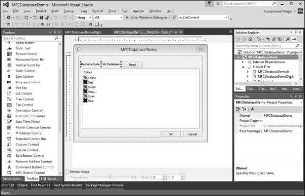
Step 2 − Add click event handler for button and control variable m_ListControl for List Control.
Step 3 − We have simple database which contains one Employees table with some records as shown in the following snapshot.
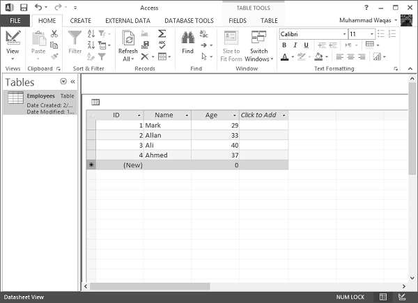
Step 4 − We need to include the following headers file so that we can use CDatabase class.
#include "odbcinst.h"
#include "afxdb.h"
Insert Query
The SQL INSERT INTO Statement is used to add new rows of data to a table in the database.
Step 1 − To add new records, we will use the ExecuteSQL() function of CDatabase class as shown in the following code.
CDatabase database;
CString SqlString;
CString strID, strName, strAge;
CString sDriver = L"MICROSOFT ACCESS DRIVER (*.mdb)";
CString sDsn;
CString sFile = L"D:\\Test.mdb";
// You must change above path if it's different
int iRec = 0;

// Build ODBC connection string
sDsn.Format(L"ODBC;DRIVER={%s};DSN='';DBQ=%s", sDriver, sFile);
TRY {
   // Open the database
   database.Open(NULL,false,false,sDsn);

   SqlString = "INSERT INTO Employees (ID,Name,age) VALUES (5,'Sanjay',69)";
   database.ExecuteSQL(SqlString);
   // Close the database
   database.Close();
}CATCH(CDBException, e) {
   // If a database exception occured, show error msg
   AfxMessageBox(L"Database error: " + e→m_strError);
}
END_CATCH;
Step 2 − When the above code is compiled and executed, you will see that a new record is added in your database.
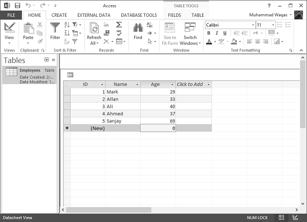
Retrieve Record
To retrieve the above table in MFC application, we implement the database related operations in the button event handler as shown in the following steps.
Step 1 − To use CDatabase, construct a CDatabase object and call its Open() function. This will open the connection.
Step 2 − Construct CRecordset objects for operating on the connected data source, pass the recordset constructor a pointer to your CDatabase object.
Step 3 − After using the connection, call the Close function and destroy the CDatabase object.
void CMFCDatabaseDemoDlg::OnBnClickedButtonRead() {
   // TODO: Add your control notification handler code here
   CDatabase database;
   CString SqlString;
   CString strID, strName, strAge;
   CString sDriver = "MICROSOFT ACCESS DRIVER (*.mdb)";
   CString sFile = L"D:\\Test.mdb";
   // You must change above path if it's different
   int iRec = 0;

   // Build ODBC connection string
   sDsn.Format("ODBC;DRIVER={%s};DSN='';DBQ=%s",sDriver,sFile);
   TRY {
      // Open the database
      database.Open(NULL,false,false,sDsn);

      // Allocate the recordset
      CRecordset recset( &database );

      // Build the SQL statement
      SqlString = "SELECT ID, Name, Age " "FROM Employees";

      // Execute the query

      recset.Open(CRecordset::forwardOnly,SqlString,CRecordset::readOnly);
      // Reset List control if there is any data
      ResetListControl();
      // populate Grids
      ListView_SetExtendedListViewStyle(m_ListControl,LVS_EX_GRIDLINES);

      // Column width and heading
      m_ListControl.InsertColumn(0,"Emp ID",LVCFMT_LEFT,-1,0);
      m_ListControl.InsertColumn(1,"Name",LVCFMT_LEFT,-1,1);
      m_ListControl.InsertColumn(2, "Age", LVCFMT_LEFT, -1, 1);
      m_ListControl.SetColumnWidth(0, 120);
      m_ListControl.SetColumnWidth(1, 200);
      m_ListControl.SetColumnWidth(2, 200);

      // Loop through each record
      while( !recset.IsEOF() ) {
         // Copy each column into a variable
         recset.GetFieldValue("ID",strID);
         recset.GetFieldValue("Name",strName);
         recset.GetFieldValue("Age", strAge);

         // Insert values into the list control
         iRec = m_ListControl.InsertItem(0,strID,0);
         m_ListControl.SetItemText(0,1,strName);
         m_ListControl.SetItemText(0, 2, strAge);

         // goto next record
         recset.MoveNext();
      }
      // Close the database
      database.Close();
   }CATCH(CDBException, e) {
      // If a database exception occured, show error msg
      AfxMessageBox("Database error: "+e→m_strError);
   }
   END_CATCH;
}

// Reset List control
void CMFCDatabaseDemoDlg::ResetListControl() {
   m_ListControl.DeleteAllItems();
   int iNbrOfColumns;
   CHeaderCtrl* pHeader = (CHeaderCtrl*)m_ListControl.GetDlgItem(0);
   if (pHeader) {
      iNbrOfColumns = pHeader→GetItemCount();
   }
   for (int i = iNbrOfColumns; i >= 0; i--) {
      m_ListControl.DeleteColumn(i);
   }
}
Step 4 − Here is the header file.
// MFCDatabaseDemoDlg.h : header file
//

#pragma once
#include "afxcmn.h"


// CMFCDatabaseDemoDlg dialog
class CMFCDatabaseDemoDlg : public CDialogEx {
   // Construction
   public:
      CMFCDatabaseDemoDlg(CWnd* pParent = NULL);    // standard constructor

   // Dialog Data
   #ifdef AFX_DESIGN_TIME
      enum { IDD = IDD_MFCDATABASEDEMO_DIALOG };
   #endif

   protected:
      virtual void DoDataExchange(CDataExchange* pDX);    // DDX/DDV support
      void ResetListControl();

   // Implementation
   protected:
      HICON m_hIcon;

      // Generated message map functions
      virtual BOOL OnInitDialog();
      afx_msg void OnPaint();
      afx_msg HCURSOR OnQueryDragIcon();
      DECLARE_MESSAGE_MAP()
   public:
      CListCtrl m_ListControl;
      afx_msg void OnBnClickedButtonRead();
};
Step 5 − When the above code is compiled and executed, you will see the following output.
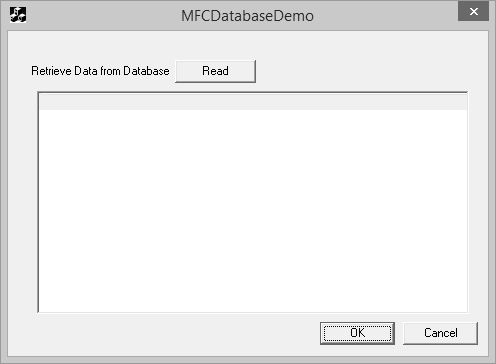
Step 6 − Press the Read button to execute the database operations. It will retrieve the Employees table.
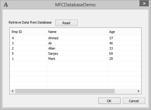
Update Record
The SQL UPDATE Query is used to modify the existing records in a table. You can use WHERE clause with UPDATE query to update selected rows otherwise all the rows would be affected.
Step 1 − Let us look into a simple example by updating the Age where ID is equal to 5.
SqlString = L"UPDATE Employees SET Age = 59 WHERE ID = 5;";
database.ExecuteSQL(SqlString);
Step 2 − Here is the complete code of button click event.
void CMFCDatabaseDemoDlg::OnBnClickedButtonRead() {
   // TODO: Add your control notification handler code here
   CDatabase database;
   CString SqlString;
   CString strID, strName, strAge;
   CString sDriver = L"MICROSOFT ACCESS DRIVER (*.mdb)";
   CString sDsn;
   CString sFile =
      L"C:\\Users\\Muhammad.Waqas\\Downloads\\Compressed\\ReadDB_demo\\Test.mdb";
   // You must change above path if it's different
   int iRec = 0;

   // Build ODBC connection string
   sDsn.Format(L"ODBC;DRIVER={%s};DSN='';DBQ=%s", sDriver, sFile);
   TRY {
      // Open the database
      database.Open(NULL,false,false,sDsn);

      // Allocate the recordset
      CRecordset recset(&database);

      SqlString = L"UPDATE Employees SET Age = 59 WHERE ID = 5;";

      database.ExecuteSQL(SqlString);

      SqlString = "SELECT ID, Name, Age FROM Employees";

      // Build the SQL statement
      SqlString = "SELECT ID, Name, Age FROM Employees";

      // Execute the query
      recset.Open(CRecordset::forwardOnly,SqlString,CRecordset::readOnly);

      // Reset List control if there is any data
      ResetListControl();
      // populate Grids
      ListView_SetExtendedListViewStyle(m_listCtrl,LVS_EX_GRIDLINES);

      // Column width and heading
      m_listCtrl.InsertColumn(0,L"Emp ID",LVCFMT_LEFT,-1,0);
      m_listCtrl.InsertColumn(1,L"Name",LVCFMT_LEFT,-1,1);
      m_listCtrl.InsertColumn(2, L"Age", LVCFMT_LEFT, -1, 1);
      m_listCtrl.SetColumnWidth(0, 120);
      m_listCtrl.SetColumnWidth(1, 200);
      m_listCtrl.SetColumnWidth(2, 200);

      // Loop through each record
      while (!recset.IsEOF()) {
         // Copy each column into a variable
         recset.GetFieldValue(L"ID",strID);
         recset.GetFieldValue(L"Name",strName);
         recset.GetFieldValue(L"Age", strAge);

         // Insert values into the list control
         iRec = m_listCtrl.InsertItem(0,strID,0);
         m_listCtrl.SetItemText(0,1,strName);
         m_listCtrl.SetItemText(0, 2, strAge);

         // goto next record
         recset.MoveNext();
      }

      // Close the database
      database.Close();
   }CATCH(CDBException, e) {
      // If a database exception occured, show error msg
      AfxMessageBox(L"Database error: " + e→m_strError);
   }
   END_CATCH;
}
Step 3 − When the above code is compiled and executed, you will see the following output.
Step 4 − Press the Read button to execute the database operations. It will retrieve the following Employees table.
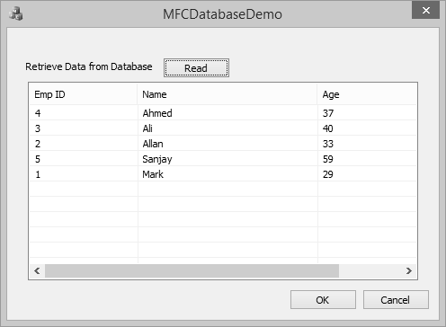
Step 5 − You can now see that age is updated from 69 to 59.
Delete Record
The SQL DELETE Query is used to delete the existing records from a table. You can use WHERE clause with DELETE query to delete selected rows, otherwise all the records would be deleted.
Step 1 − Let us look into a simple example by deleting the record where ID is equal to 3.
SqlString = L"DELETE FROM Employees WHERE ID = 3;";

database.ExecuteSQL(SqlString);
Step 2 − Here is the complete code of button click event.
void CMFCDatabaseDemoDlg::OnBnClickedButtonRead() {
   // TODO: Add your control notification handler code here
   CDatabase database;
   CString SqlString;
   CString strID, strName, strAge;
   CString sDriver = L"MICROSOFT ACCESS DRIVER (*.mdb)";
   CString sDsn;
   CString sFile =
       L"C:\\Users\\Muhammad.Waqas\\Downloads\\Compressed\\ReadDB_demo\\Test.mdb";

   // You must change above path if it's different
   int iRec = 0;

   // Build ODBC connection string
   sDsn.Format(L"ODBC;DRIVER={%s};DSN='';DBQ=%s", sDriver, sFile);
   TRY {
      // Open the database
      database.Open(NULL,false,false,sDsn);

      // Allocate the recordset
      CRecordset recset(&database);

      SqlString = L"DELETE FROM Employees WHERE ID = 3;";

      database.ExecuteSQL(SqlString);

      SqlString = "SELECT ID, Name, Age FROM Employees";

      // Build the SQL statement
      SqlString = "SELECT ID, Name, Age FROM Employees";

      // Execute the query
      recset.Open(CRecordset::forwardOnly,SqlString,CRecordset::readOnly);

      // Reset List control if there is any data
      ResetListControl();
      // populate Grids
      ListView_SetExtendedListViewStyle(m_listCtrl,LVS_EX_GRIDLINES);
      // Column width and heading
      m_listCtrl.InsertColumn(0,L"Emp ID",LVCFMT_LEFT,-1,0);
      m_listCtrl.InsertColumn(1,L"Name",LVCFMT_LEFT,-1,1);
      m_listCtrl.InsertColumn(2, L"Age", LVCFMT_LEFT, -1, 1);
      m_listCtrl.SetColumnWidth(0, 120);
      m_listCtrl.SetColumnWidth(1, 200);
      m_listCtrl.SetColumnWidth(2, 200);

      // Loop through each record
      while (!recset.IsEOF()) {
         // Copy each column into a variable
         recset.GetFieldValue(L"ID",strID);
         recset.GetFieldValue(L"Name",strName);
         recset.GetFieldValue(L"Age", strAge);

         // Insert values into the list control
         iRec = m_listCtrl.InsertItem(0,strID,0);
         m_listCtrl.SetItemText(0,1,strName);
         m_listCtrl.SetItemText(0, 2, strAge);

         // goto next record
         recset.MoveNext();
      }
      // Close the database
      database.Close();
   }CATCH(CDBException, e) {
      // If a database exception occured, show error msg
      AfxMessageBox(L"Database error: " + e→m_strError);
   }
   END_CATCH;
}
Step 3 − When the above code is compiled and executed, you will see the following output.
Step 4 − Press the Read button to execute the database operations. It will retrieve the Employees table.
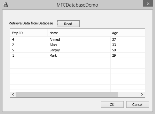
MFC - Serialization
Serialization is the process of writing or reading an object to or from a persistent storage medium such as a disk file. Serialization is ideal for situations where it is desired to maintain the state of structured data (such as C++ classes or structures) during or after the execution of a program.
When performing file processing, the values are typically of primitive types (char, short, int, float, or double). In the same way, we can individually save many values, one at a time. This technique doesn't include an object created from (as a variable of) a class.
The MFC library has a high level of support for serialization. It starts with the CObject class that is the ancestor to most MFC classes, which is equipped with a Serialize() member function.
Let us look into a simple example by creating a new MFC project.
Step 1 − Remove the TODO line and design your dialog box as shown in the following snapshot.
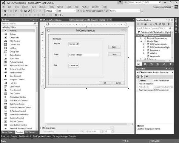
Step 2 − Add value variables for all the edit controls. For Emp ID and Age mentioned, the value type is an integer as shown in the following snapshot.
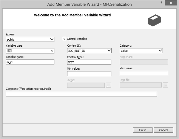
Step 3 − Add the event handler for both the buttons.
Step 4 − Let us now add a simple Employee class, which we need to serialize. Here is the declaration of Employee class in header file.
class CEmployee : public CObject {
   public:
      int empID;
      CString empName;
      int age;
      CEmployee(void);
      ~CEmployee(void);
   private:

   public:
      void Serialize(CArchive& ar);
      DECLARE_SERIAL(CEmployee);
};
Step 5 − Here is the definition of Employee class in source (*.cpp) file.
IMPLEMENT_SERIAL(CEmployee, CObject, 0)
CEmployee::CEmployee(void) {

}

CEmployee::~CEmployee(void) {

}

void CEmployee::Serialize(CArchive& ar) {
   CObject::Serialize(ar);

   if (ar.IsStoring())
      ar << empID << empName << age;
   else
      ar >> empID >> empName >> age;
}
Step 6 − Here is the implementation of Save button event handler.
void CMFCSerializationDlg::OnBnClickedButtonSave() {
   // TODO: Add your control notification handler code here
   UpdateData(TRUE);
   CEmployee employee;
   CFile file;
   file.Open(L"EmployeeInfo.hse", CFile::modeCreate | CFile::modeWrite);
   CArchive ar(&file, CArchive::store);
   employee.empID = m_id;
   employee.empName = m_strName;
   employee.age = m_age;
   employee.Serialize(ar);
   ar.Close();
}
Step 7 − Here is the implementation of Open button event handler.
void CMFCSerializationDlg::OnBnClickedButtonOpen() {
   // TODO: Add your control notification handler code here
   UpdateData(TRUE);

   CFile file;

   file.Open(L"EmployeeInfo.hse", CFile::modeRead);
   CArchive ar(&file, CArchive::load);
   CEmployee employee;

   employee.Serialize(ar);

   m_id = employee.empID;
   m_strName = employee.empName;
   m_age = employee.age;
   ar.Close();
   file.Close();

   UpdateData(FALSE);
}
Step 8 − When the above code is compiled and executed, you will see the following output.
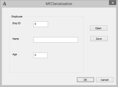
Step 9 − Enter the info in all the fields and click Save and close this program.
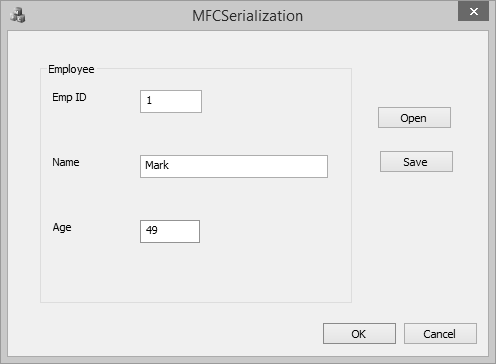
Step 10 − It will save the data. Run the application again and click open. It will load the Employee information.
MFC - Multithreading
The Microsoft Foundation Class (MFC) library provides support for multithreaded applications. A thread is a path of execution within a process. When you start Notepad, the operating system creates a process and begins executing the primary thread of that process. When this thread terminates, so does the process.
You can create additional threads in your application if you want. All threads in MFC applications are represented by CWinThread objects. In most situations, you do not even have to explicitly create these objects; instead call the framework helper function AfxBeginThread, which creates the CWinThread object for you.
Let us look into a simple example by creating a new MFC dialog based application.
Step 1 − Change the Caption and ID of Static control to Click on Start Thread button and IDC_STATIC_TEXT respectively.
Step 2 − Drag two buttons and add click event handlers for these buttons.
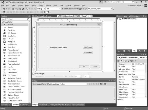
Step 3 − Add control variable for static text control.
Step 4 − Now add the following three global variables at the start of CMFCMultithreadingDlg.cpp file.
int currValue;
int maxValue;
BOOL stopNow;
Step 5 − Add the WM_TIMER message in CMFCMultithreadingDlg class.
Here is the implementation of OnTimer()
void CMFCMultithreadingDlg::OnTimer(UINT_PTR nIDEvent) {
   // TODO: Add your message handler code here and/or call default
   CString sStatusMsg;
   sStatusMsg.Format(L"Running: %d", currValue);
   m_ctrlStatus.SetWindowText(sStatusMsg);

   CDialogEx::OnTimer(nIDEvent);
}
Step 6 − Now add a sample function for using in AfxBeginThread in CMFCMultithreadingDlg class.
UINT MyThreadProc(LPVOID Param) {
   while (!stopNow && (currValue < maxValue)) {
      currValue++;
      Sleep(50);     // would do some work here
   }

   return TRUE;
}
Step 7 − Here is the implementation of event handler for Start Thread button, which will start the thread.
void CMFCMultithreadingDlg::OnBnClickedButtonStart() {
   // TODO: Add your control notification handler code here
   currValue = 0;
   maxValue = 5000;
   stopNow = 0;
   m_ctrlStatus.SetWindowText(L"Starting...");
   SetTimer(1234, 333, 0); // 3 times per second

   AfxBeginThread(MyThreadProc, 0); // <<== START THE THREAD
}
Step 8 − Here is the implementation of event handler for Stop Thread button, which will stop the thread.
void CMFCMultithreadingDlg::OnBnClickedButtonStop() {

   // TODO: Add your control notification handler code here
   stopNow = TRUE;
   KillTimer(1234);
   m_ctrlStatus.SetWindowText(L"Stopped");
}
Step 9 − Here is the complete source file.
// MFCMultithreadingDlg.cpp : implementation file
//

#include "stdafx.h"
#include "MFCMultithreading.h"
#include "MFCMultithreadingDlg.h"
#include "afxdialogex.h"

#ifdef _DEBUG
#define new DEBUG_NEW
#endif

// CMFCMultithreadingDlg dialog

int currValue;
int maxValue;
BOOL stopNow;

CMFCMultithreadingDlg::CMFCMultithreadingDlg(CWnd* pParent /* = NULL*/)
   : CDialogEx(IDD_MFCMULTITHREADING_DIALOG, pParent) {
   m_hIcon = AfxGetApp() -> LoadIcon(IDR_MAINFRAME);
}
void CMFCMultithreadingDlg::DoDataExchange(CDataExchange* pDX) {
   CDialogEx::DoDataExchange(pDX);
   DDX_Control(pDX, IDC_STATIC_TEXT, m_ctrlStatus);
}

BEGIN_MESSAGE_MAP(CMFCMultithreadingDlg, CDialogEx)
   ON_WM_PAINT()
   ON_WM_QUERYDRAGICON()
   ON_BN_CLICKED(IDC_BUTTON_START,
      &CMFCMultithreadingDlg::OnBnClickedButtonStart)
   ON_WM_TIMER()
   ON_BN_CLICKED(IDC_BUTTON_STOP,
      &CMFCMultithreadingDlg::OnBnClickedButtonStop)
END_MESSAGE_MAP()

// CMFCMultithreadingDlg message handlers

BOOL CMFCMultithreadingDlg::OnInitDialog() {
   CDialogEx::OnInitDialog();

   // Set the icon for this dialog. The framework does this automatically
   // when the application's main window is not a dialog
   SetIcon(m_hIcon, TRUE);        // Set big icon
   SetIcon(m_hIcon, FALSE);       // Set small icon

   // TODO: Add extra initialization here

   return TRUE; // return TRUE unless you set the focus to a control
}

// If you add a minimize button to your dialog, you will need the code below
// to draw the icon. For MFC applications using the document/view model,
// this is automatically done for you by the framework.

void CMFCMultithreadingDlg::OnPaint() {
   if (IsIconic()) {
      CPaintDC dc(this); // device context for painting
      SendMessage(WM_ICONERASEBKGND,
         reinterpret_cast<WPARAM>(dc.GetSafeHdc()), 0);

      // Center icon in client rectangle
      int cxIcon = GetSystemMetrics(SM_CXICON);
      int cyIcon = GetSystemMetrics(SM_CYICON);
      CRect rect;
      GetClientRect(&rect);
      int x = (rect.Width() - cxIcon + 1) / 2;
      int y = (rect.Height() - cyIcon + 1) / 2;

      // Draw the icon
      dc.DrawIcon(x, y, m_hIcon);
   }else {
      CDialogEx::OnPaint();
   }
}
// The system calls this function to obtain the cursor to display while the user drags
// the minimized window.
HCURSOR CMFCMultithreadingDlg::OnQueryDragIcon() {
   return static_cast<HCURSOR>(m_hIcon);
}

UINT /*CThreadDlg::*/MyThreadProc(LPVOID Param) //Sample function for using in
AfxBeginThread {
   while (!stopNow && (currValue < maxValue)) {
      currValue++;
      Sleep(50); // would do some work here
   }
   return TRUE;
}
void CMFCMultithreadingDlg::OnBnClickedButtonStart() {
   // TODO: Add your control notification handler code here
   currValue = 0;
   maxValue = 5000;
   stopNow = 0;
   m_ctrlStatus.SetWindowText(L"Starting...");
   SetTimer(1234, 333, 0); // 3 times per second

   AfxBeginThread(MyThreadProc, 0); // <<== START THE THREAD
}

void CMFCMultithreadingDlg::OnTimer(UINT_PTR nIDEvent) {
   // TODO: Add your message handler code here and/or call default
   CString sStatusMsg;
   sStatusMsg.Format(L"Running: %d", currValue);
   m_ctrlStatus.SetWindowText(sStatusMsg);

   CDialogEx::OnTimer(nIDEvent);
}

void CMFCMultithreadingDlg::OnBnClickedButtonStop() {
   // TODO: Add your control notification handler code here
   stopNow = TRUE;
   KillTimer(1234);
   m_ctrlStatus.SetWindowText(L"Stopped");
}
Step 10 − When the above code is compiled and executed, you will see the following output.
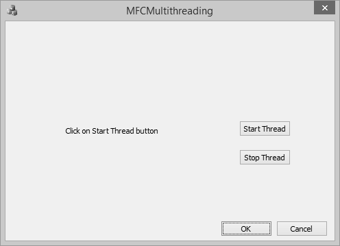
Step 11 − Now click on Start Thread button.
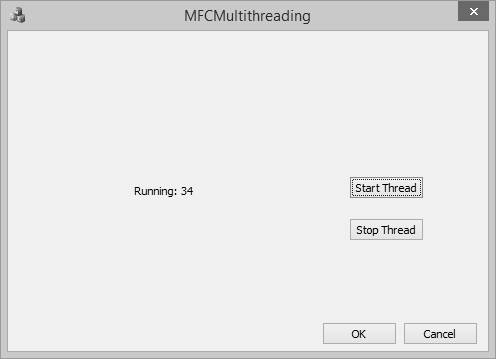
Step 12 − Click the Stop Thread button. It will stop the thread.
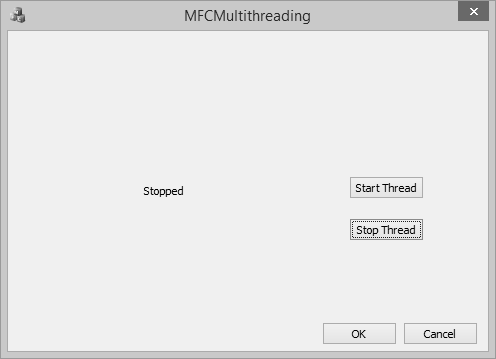
MFC - Internet Programming
Microsoft provides many APIs for programming both client and server applications. Many new applications are being written for the Internet, and as technologies, browser capabilities, and security options change, new types of applications will be written. Your custom application can retrieve information and provide data on the Internet.
MFC provides a class CSocket for writing network communications programs with Windows Sockets.
Here is a list of methods in CSocket class.
| Sr.No. | Name & Description |
|---|---|
| 1 | Attach Attaches a SOCKET handle to a CSocket object. |
| 2 | CancelBlockingCall Cancels a blocking call that is currently in progress. |
| 3 | Create Creates a socket. |
| 4 | FromHandle Returns a pointer to a CSocket object, given a SOCKET handle. |
| 5 | IsBlocking Determines whether a blocking call is in progress. |
Let us look into a simple example by creating a MFS SDI application.
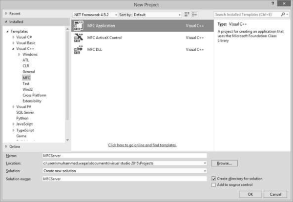
Step 1 − Enter MFCServer in the name field and click OK.
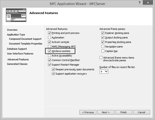
Step 2 − On Advanced Features tab, check the Windows sockets option.
Step 3 − Once the project is created, add a new MFC class CServerSocket.
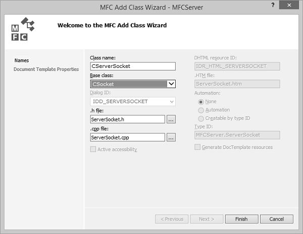
Step 4 − Select the CSocket as base class and click Finish.
Step 5 − Add more MFC class CReceivingSocket.
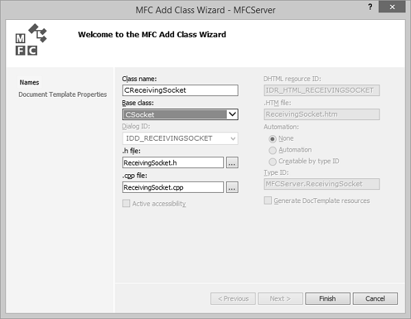
Step 6 − CRecevingSocket will receive incoming messages from client.
In CMFCServerApp, the header file includes the following files −
#include "ServerSocket.h"
#include "MFCServerView.h"
Step 7 − Add the following two class variables in CMFCServerApp class.
CServerSocket m_serverSocket;
CMFCServerView m_pServerView;
Step 8 − In CMFCServerApp::InitInstance() method, create the socket and specify the port and then call the Listen method as shown below.
m_serverSocket.Create(6666);
m_serverSocket.Listen();
Step 9 − Include the following header file in CMFCServerView header file.
#include "MFCServerDoc.h"
Step 10 − Override the OnAccept function from Socket class.
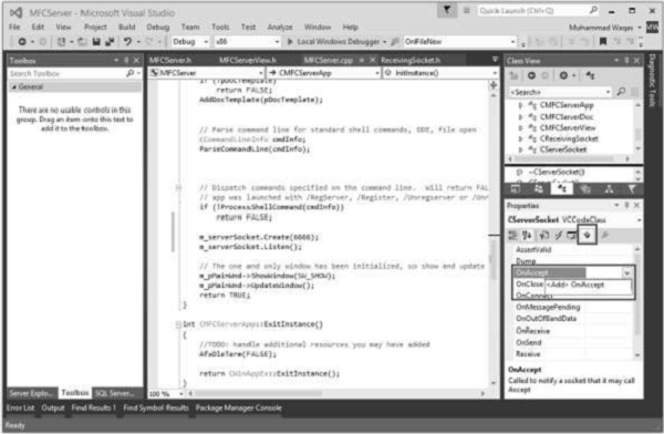
Step 11 − Select CServerSocket in class view and the highlighted icon in Properties window. Now, Add OnAccept. Here is the implementation of OnAccept function.
void CServerSocket::OnAccept(int nErrorCode) {

   // TODO: Add your specialized code here and/or call the base class
   AfxMessageBox(L"Connection accepted");
   CSocket::OnAccept(nErrorCode);
}
Step 12 − Add OnReceive() function.
void CServerSocket::OnReceive(int nErrorCode) {

   // TODO: Add your specialized code here and/or call the base class
   AfxMessageBox(L"Data Received");
   CSocket::OnReceive(nErrorCode);
}
Step 13 − Add OnReceive() function in CReceivingSocket class.
Right-click on the CMFCServerView class in solution explorer and select Add → AddFunction.
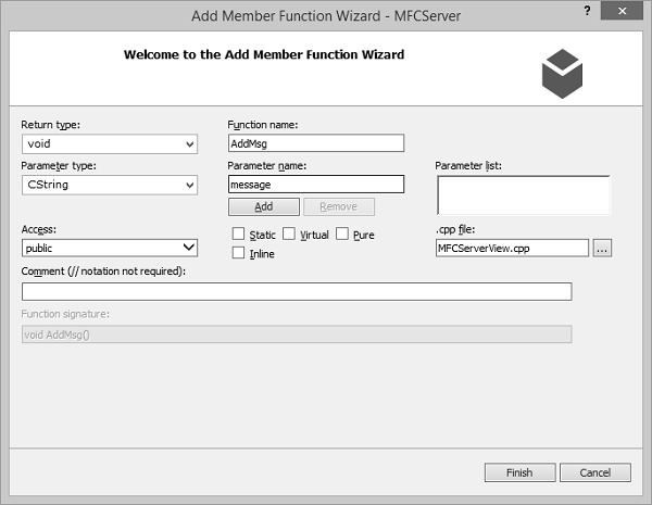
Step 14 − Enter the above mentioned information and click finish.
Step 15 − Add the following CStringArray variable in CMFCServerView header file.
CStringArray m_msgArray;
Step 16 − Here is the implementation of AddMsg() function.
void CMFCServerView::AddMsg(CString message) {

   m_msgArray.Add(message);
   Invalidate();
}
Step 17 − Update the constructor as shown in the following code.
CMFCServerView::CMFCServerView() {

   ((CMFCServerApp*)AfxGetApp()) -> m_pServerView = this;
}
Step 18 − Here is the implementation of OnDraw() function, which display messages.
void CMFCServerView::OnDraw(CDC* pDC) {

   int y = 100;
   for (int i = 0; m_msgArray.GetSize(); i++) {

      pDC->TextOut(100, y, m_msgArray.GetAt(i));
      y += 50;
   }
   CMFCServerDoc* pDoc = GetDocument();
   ASSERT_VALID(pDoc);
   if (!pDoc)
      return;

   // TODO: add draw code for native data here
}
Step 19 − The server side is now complete. It will receive message from the client.
Create Client Side Application
Step 1 − Let us create a new MFC dialog based application for client side application.
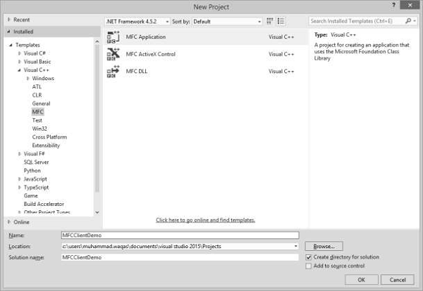
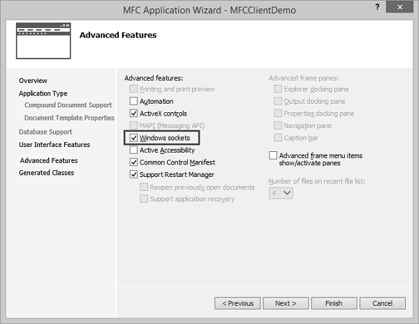
Step 2 − On Advanced Features tab, check the Windows sockets option as shown above.
Step 3 − Once the project is created, design your dialog box as shown in the following snapshot.
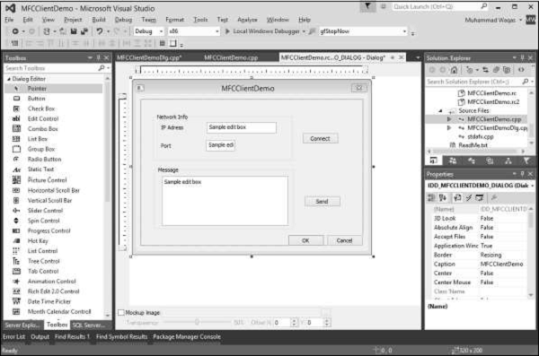
Step 4 − Add event handlers for Connect and Send buttons.
Step 5 − Add value variables for all the three edit controls. For port edit control, select the variable type UINT.

Step 6 − Add MFC class for connecting and sending messages.
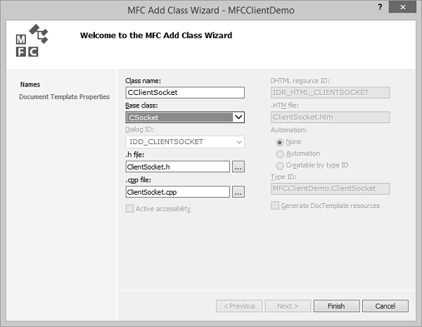
Step 7 − Include the header file of CClientSocket class in the header file CMFCClientDemoApp class and add the class variable. Similarly, add the class variable in CMFCClientDemoDlg header file as well.
CClientSocket m_clientSocket;
Step 8 − Here is the implementation of Connect button event handler.
void CMFCClientDemoDlg::OnBnClickedButtonConnect() {

   // TODO: Add your control notification handler code here
   UpdateData(TRUE);
   m_clientSocket.Create();
   if (m_clientSocket.Connect(m_ipAddress, m_port)) {
      AfxMessageBox(L"Connection Successfull");
   }else {
      AfxMessageBox(L"Connection Failed");
   }
   DWORD error = GetLastError();
}
Step 9 − Here is the implementation of Send button event handler.
void CMFCClientDemoDlg::OnBnClickedButtonSend() {

   // TODO: Add your control notification handler code here
   UpdateData(TRUE);
   if (m_clientSocket.Send(m_message.GetBuffer(m_message.GetLength()), m_message.GetLength())) {

   }else {
      AfxMessageBox(L"Failed to send message");
   }
}
Step 10 − First run the Server application and then the client application. Enter the local host ip and port and click Connect.
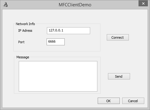
Step 11 − You will now see the message on Server side as shown in the following snapshot.
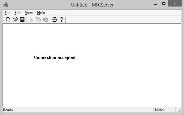
MFC - GDI
Windows provides a variety of drawing tools to use in device contexts. It provides pens to draw lines, brushes to fill interiors, and fonts to draw text. MFC provides graphic-object classes equivalent to the drawing tools in Windows.
Drawing
A device context is a Windows data structure containing information about the drawing attributes of a device such as a display or a printer. All drawing calls are made through a device-context object, which encapsulates the Windows APIs for drawing lines, shapes, and text.
Device contexts allow device-independent drawing in Windows. Device contexts can be used to draw to the screen, to the printer, or to a metafile.
CDC is the most fundamental class to draw in MFC. The CDC object provides member functions to perform the basic drawing steps, as well as members for working with a display context associated with the client area of a window.
| Sr. No. | Name & Description |
|---|---|
| 1 | AbortDoc Terminates the current print job, erasing everything the application has written to the device since the last call of the StartDoc member function. |
| 2 | AbortPath Closes and discards any paths in the device context. |
| 3 | AddMetaFileComment Copies the comment from a buffer into a specified enhanced-format metafile. |
| 4 | AlphaBlend Displays bitmaps that have transparent or semitransparent pixels. |
| 5 | AngleArc Draws a line segment and an arc, and moves the current position to the ending point of the arc. |
| 6 | Arc Draws an elliptical arc. |
| 7 | ArcTo Draws an elliptical arc. This function is similar to Arc, except that the current position is updated. |
| 8 | Attach Attaches a Windows device context to this CDC object. |
| 9 | BeginPath Opens a path bracket in the device context. |
| 10 | BitBlt Copies a bitmap from a specified device context. |
| 11 | Chord Draws a chord (a closed figure bounded by the intersection of an ellipse and a line segment). |
| 12 | CloseFigure Closes an open figure in a path. |
| 13 | CreateCompatibleDC Creates a memory-device context that is compatible with another device context. You can use it to prepare images in memory. |
| 14 | CreateDC Creates a device context for a specific device. |
| 15 | CreateIC Creates an information context for a specific device. This provides a fast way to get information about the device without creating a device context. |
| 16 | DeleteDC Deletes the Windows device context associated with this CDC object. |
| 17 | DeleteTempMap Called by the CWinApp idle-time handler to delete any temporary CDC object created by FromHandle. Also detaches the device context. |
| 18 | Detach Detaches the Windows device context from this CDC object. |
| 19 | DPtoHIMETRIC Converts device units into HIMETRIC units. |
| 20 | DPtoLP Converts device units into logical units. |
| 21 | Draw3dRect Draws a three-dimensional rectangle. |
| 22 | DrawDragRect Erases and redraws a rectangle as it is dragged. |
| 23 | DrawEdge Draws the edges of a rectangle. |
| 24 | DrawEscape Accesses drawing capabilities of a video display that are not directly available through the graphics device interface (GDI). |
| 25 | DrawFocusRect Draws a rectangle in the style used to indicate focus. |
| 26 | DrawFrameControl Draw a frame control. |
| 27 | DrawIcon Draws an icon. |
| 28 | DrawState Displays an image and applies a visual effect to indicate a state. |
| 29 | DrawText Draws formatted text in the specified rectangle. |
| 30 | DrawTextEx Draws formatted text in the specified rectangle using additional formats. |
| 31 | Ellipse Draws an ellipse. |
| 32 | EndDoc Ends a print job started by the StartDoc member function. |
| 33 | EndPage Informs the device driver that a page is ending. |
| 34 | EndPath Closes a path bracket and selects the path defined by the bracket into the device context. |
| 35 | EnumObjects Enumerates the pens and brushes available in a device context. |
| 36 | Escape Allows applications to access facilities that are not directly available from a particular device through GDI. Also allows access to Windows escape functions. Escape calls made by an application are translated and sent to the device driver. |
| 37 | ExcludeClipRect Creates a new clipping region that consists of the existing clipping region minus the specified rectangle. |
| 38 | ExcludeUpdateRgn Prevents drawing within invalid areas of a window by excluding an updated region in the window from a clipping region. |
| 39 | ExtFloodFill Fills an area with the current brush. Provides more flexibility than the FloodFill member function. |
| 40 | ExtTextOut Writes a character string within a rectangular region using the currently selected font. |
| 41 | FillPath Closes any open figures in the current path and fills the path's interior by using the current brush and polygonfilling mode. |
| 42 | FillRect Fills a given rectangle by using a specific brush. |
| 43 | FillRgn Fills a specific region with the specified brush. |
| 44 | FillSolidRect Fills a rectangle with a solid color. |
| 45 | FlattenPath Transforms any curves in the path selected into the current device context, and turns each curve into a sequence of lines. |
| 46 | FloodFill Fills an area with the current brush. |
| 47 | FrameRect Draws a border around a rectangle. |
| 48 | FrameRgn Draws a border around a specific region using a brush. |
| 49 | FromHandle Returns a pointer to a CDC object when given a handle to a device context. If a CDC object is not attached to the handle, a temporary CDC object is created and attached. |
| 50 | GetArcDirection Returns the current arc direction for the device context. |
| 51 | GetAspectRatioFilter Retrieves the setting for the current aspect-ratio filter. |
| 52 | GetBkColor Retrieves the current background color. |
| 53 | GetBkMode Retrieves the background mode. |
| 54 | GetBoundsRect Returns the current accumulated bounding rectangle for the specified device context. |
| 55 | GetBrushOrg Retrieves the origin of the current brush. |
| 56 | GetCharABCWidths Retrieves the widths, in logical units, of consecutive characters in a given range from the current font. |
| 57 | GetCharABCWidthsI Retrieves the widths, in logical units, of consecutive glyph indices in a specified range from the current TrueType font. |
| 58 | GetCharacterPlacement Retrieves various types of information on a character string. |
| 59 | GetCharWidth Retrieves the fractional widths of consecutive characters in a given range from the current font. |
| 60 | GetCharWidthI Retrieves the widths, in logical coordinates, of consecutive glyph indices in a specified range from the current font. |
| 61 | GetClipBox Retrieves the dimensions of the tightest bounding rectangle around the current clipping boundary. |
| 62 | GetColorAdjustment Retrieves the color adjustment values for the device context. |
| 63 | GetCurrentBitmap Returns a pointer to the currently selected CBitmap object. |
| 64 | GetCurrentBrush Returns a pointer to the currently selected CBrush object. |
| 65 | GetCurrentFont Returns a pointer to the currently selected CFont object. |
| 66 | GetCurrentPalette Returns a pointer to the currently selected CPalette object. |
| 48 | GetCurrentPen Returns a pointer to the currently selected CPen object. |
| 67 | GetCurrentPosition Retrieves the current position of the pen (in logical coordinates). |
| 68 | GetDCBrushColor Retrieves the current brush color. |
| 69 | GetDCPenColor Retrieves the current pen color. |
| 70 | GetDeviceCaps Retrieves a specified kind of device-specific information about a given display device's capabilities. |
| 71 | GetFontData Retrieves font metric information from a scalable font file. The information to retrieve is identified by specifying an offset into the font file and the length of the information to return. |
| 72 | GetFontLanguageInfo Returns information about the currently selected font for the specified display context. |
| 73 | GetGlyphOutline Retrieves the outline curve or bitmap for an outline character in the current font. |
| 74 | GetGraphicsMode Retrieves the current graphics mode for the specified device context. |
| 75 | GetHalftoneBrush Retrieves a halftone brush. |
| 76 | GetKerningPairs Retrieves the character kerning pairs for the font that is currently selected in the specified device context. |
| 77 | GetLayout Retrieves the layout of a device context (DC). The layout can be either left to right (default) or right to left (mirrored). |
| 78 | GetMapMode Retrieves the current mapping mode. |
| 79 | GetMiterLimit Returns the miter limit for the device context. |
| 80 | GetNearestColor Retrieves the closest logical color to a specified logical color that the given device can represent. |
| 81 | GetOutlineTextMetrics Retrieves font metric information for TrueType fonts. |
| 82 | GetOutputCharWidth Retrieves the widths of individual characters in a consecutive group of characters from the current font using the output device context. |
| 83 | GetOutputTabbedTextExtent Computes the width and height of a character string on the output device context. |
| 84 | GetOutputTextExtent Computes the width and height of a line of text on the output device context using the current font to determine the dimensions. |
| 85 | GetOutputTextMetrics Retrieves the metrics for the current font from the output device context. |
| 86 | GetPath Retrieves the coordinates defining the endpoints of lines and the control points of curves found in the path that is selected into the device context. |
| 87 | GetPixel Retrieves the RGB color value of the pixel at the specified point. |
| 88 | GetPolyFillMode Retrieves the current polygon-filling mode. |
| 89 | GetROP2 Retrieves the current drawing mode. |
| 90 | GetSafeHdc Returns m_hDC, the output device context. |
| 91 | GetStretchBltMode Retrieves the current bitmap-stretching mode. |
| 92 | GetTabbedTextExtent Computes the width and height of a character string on the attribute device context. |
| 93 | GetTextAlign Retrieves the text-alignment flags. |
| 94 | GetTextCharacterExtra Retrieves the current setting for the amount of intercharacter spacing. |
| 95 | GetTextColor Retrieves the current text color. |
| 96 | GetTextExtent Computes the width and height of a line of text on the attribute device context using the current font to determine the dimensions. |
| 97 | GetTextExtentExPointI Retrieves the number of characters in a specified string that will fit within a specified space and fills an array with the text extent for each of those characters. |
| 98 | GetTextExtentPointI Retrieves the width and height of the specified array of glyph indices. |
| 99 | GetTextFace Copies the typeface name of the current font into a buffer as a null-terminated string. |
| 100 | GetTextMetrics Retrieves the metrics for the current font from the attribute device context. |
| 101 | GetViewportExt Retrieves the x- and y-extents of the viewport. |
| 102 | GetViewportOrg Retrieves the x- and y-coordinates of the viewport origin. |
| 103 | GetWindow Returns the window associated with the display device context. |
| 104 | GetWindowExt Retrieves the x- and y-extents of the associated window. |
| 105 | GetWindowOrg Retrieves the x- and y-coordinates of the origin of the associated window. |
| 106 | GetWorldTransform Retrieves the current world-space to page-space transformation. |
| 107 | GradientFill Fills rectangle and triangle structures with a gradating color. |
| 108 | GrayString Draws dimmed (grayed) text at the given location. |
| 109 | HIMETRICtoDP Converts HIMETRIC units into device units. |
| 110 | HIMETRICtoLP Converts HIMETRIC units into logical units. |
| 111 | IntersectClipRect Creates a new clipping region by forming the intersection of the current region and a rectangle. |
| 112 | InvertRect Inverts the contents of a rectangle. |
| 113 | InvertRgn Inverts the colors in a region. |
| 114 | IsPrinting Determines whether the device context is being used for printing. |
| 115 | LineTo Draws a line from the current position up to, but not including, a point. |
| 116 | LPtoDP Converts logical units into device units. |
| 117 | LPtoHIMETRIC Converts logical units into HIMETRIC units. |
| 118 | MaskBlt Combines the color data for the source and destination bitmaps using the given mask and raster operation. |
| 119 | ModifyWorldTransform Changes the world transformation for a device context using the specified mode. |
| 120 | MoveTo Moves the current position. |
| 121 | OffsetClipRgn Moves the clipping region of the given device. |
| 122 | OffsetViewportOrg Modifies the viewport origin relative to the coordinates of the current viewport origin. |
| 123 | OffsetWindowOrg Modifies the window origin relative to the coordinates of the current window origin. |
| 124 | PaintRgn Fills a region with the selected brush. |
| 125 | PatBlt Creates a bit pattern. |
| 126 | Pie Draws a pie-shaped wedge. |
| 127 | PlayMetaFile Plays the contents of the specified metafile on the given device. The enhanced version of PlayMetaFile displays the picture stored in the given enhanced-format metafile. The metafile can be played any number of times. |
| 128 | PlgBlt Performs a bit-block transfer of the bits of color data from the specified rectangle in the source device context to the specified parallelogram in the given device context. |
| 129 | PolyBezier Draws one or more Bzier splines. The current position is neither used nor updated. |
| 130 | PolyBezierTo Draws one or more Bzier splines, and moves the current position to the ending point of the last Bzier spline. |
| 131 | PolyDraw Draws a set of line segments and Bzier splines. This function updates the current position. |
| 132 | Polygon Draws a polygon consisting of two or more points (vertices) connected by lines. |
| 133 | Polyline Draws a set of line segments connecting the specified points. |
| 134 | PolylineTo Draws one or more straight lines and moves the current position to the ending point of the last line. |
| 135 | PolyPolygon Creates two or more polygons that are filled using the current polygon-filling mode. The polygons may be disjoint or they may overlap. |
| 136 | PolyPolyline Draws multiple series of connected line segments. The current position is neither used nor updated by this function. |
| 137 | PtVisible Specifies whether the given point is within the clipping region. |
| 138 | RealizePalette Maps palette entries in the current logical palette to the system palette. |
| 139 | Rectangle Draws a rectangle using the current pen and fills it using the current brush. |
| 140 | RectVisible Determines whether any part of the given rectangle lies within the clipping region. |
| 141 | ReleaseAttribDC Releases m_hAttribDC, the attribute device context. |
| 142 | ReleaseOutputDC Releases m_hDC, the output device context. |
| 143 | ResetDC Updates the m_hAttribDC device context. |
| 144 | RestoreDC Restores the device context to a previous state saved with SaveDC. |
| 145 | RoundRect Draws a rectangle with rounded corners using the current pen and filled using the current brush. |
| 146 | SaveDC Saves the current state of the device context. |
| 147 | ScaleViewportExt Modifies the viewport extent relative to the current values. |
| 148 | ScaleWindowExt Modifies the window extents relative to the current values. |
| 149 | ScrollDC Scrolls a rectangle of bits horizontally and vertically. |
| 150 | SelectClipPath Selects the current path as a clipping region for the device context, combining the new region with any existing clipping region by using the specified mode. |
| 151 | SelectClipRgn Combines the given region with the current clipping region by using the specified mode. |
| 152 | SelectObject Selects a GDI drawing object such as a pen. |
| 153 | SelectPalette Selects the logical palette. |
| 154 | SelectStockObject Selects one of the predefined stock pens, brushes, or fonts provided by Windows. |
| 155 | SetAbortProc Sets a programmer-supplied callback function that Windows calls if a print job must be aborted. |
| 156 | SetArcDirection Sets the drawing direction to be used for arc and rectangle functions. |
| 157 | SetAttribDC Sets m_hAttribDC, the attribute device context. |
| 158 | SetBkColor Sets the current background color. |
| 159 | SetBkMode Sets the background mode. |
| 160 | SetBoundsRect Controls the accumulation of bounding-rectangle information for the specified device context. |
| 161 | SetBrushOrg Specifies the origin for the next brush selected into a device context. |
| 162 | SetColorAdjustment Sets the color adjustment values for the device context using the specified values. |
| 163 | SetDCBrushColor Sets the current brush color. |
| 164 | SetDCPenColor Sets the current pen color. |
| 165 | SetGraphicsMode Sets the current graphics mode for the specified device context. |
| 166 | SetLayout Changes the layout of a device context (DC). |
| 167 | SetMapMode Sets the current mapping mode. |
| 168 | SetMapperFlags Alters the algorithm that the font mapper uses when it maps logical fonts to physical fonts. |
| 169 | SetMiterLimit Sets the limit for the length of miter joins for the device context. |
| 170 | SetOutputDC Sets m_hDC, the output device context. |
| 171 | SetPixel Sets the pixel at the specified point to the closest approximation of the specified color. |
| 172 | SetPixelV Sets the pixel at the specified coordinates to the closest approximation of the specified color. SetPixelV is faster than SetPixel because it does not need to return the color value of the point actually painted. |
| 173 | SetPolyFillMode Sets the polygon-filling mode. |
| 175 | SetROP2 Sets the current drawing mode. |
| 176 | SetStretchBltMode Sets the bitmap-stretching mode. |
| 177 | SetTextAlign Sets the text-alignment flags. |
| 178 | SetTextCharacterExtra Sets the amount of intercharacter spacing. |
| 179 | SetTextColor Sets the text color. |
| 180 | SetTextJustification Adds space to the break characters in a string. |
| 181 | SetViewportExt Sets the x- and y-extents of the viewport. |
| 182 | SetViewportOrg Sets the viewport origin. |
| 183 | SetWindowExt Sets the x- and y-extents of the associated window. |
| 184 | SetWindowOrg Sets the window origin of the device context. |
| 185 | SetWorldTransform Sets the current world-space to page-space transformation. |
| 186 | StartDoc Informs the device driver that a new print job is starting. |
| 187 | StartPage Informs the device driver that a new page is starting. |
| 188 | StretchBlt Moves a bitmap from a source rectangle and device into a destination rectangle, stretching or compressing the bitmap if necessary to fit the dimensions of the destination rectangle. |
| 189 | StrokeAndFillPath Closes any open figures in a path, strikes the outline of the path by using the current pen, and fills its interior by using the current brush. |
| 190 | StrokePath Renders the specified path by using the current pen. |
| 191 | TabbedTextOut Writes a character string at a specified location, expanding tabs to the values specified in an array of tab-stop positions. |
| 192 | TextOut Writes a character string at a specified location using the currently selected font. |
| 193 | TransparentBlt Transfers a bit-block of color data from the specified source device context into a destination device context, rendering a specified color transparent in the transfer. |
| 194 | UpdateColors Updates the client area of the device context by matching the current colors in the client area to the system palette on a pixel-by-pixel basis. |
| 195 | WidenPath Redefines the current path as the area that would be painted if the path were stroked using the pen currently selected into the device context. |
Lines
Step 1 − Let us look into a simple example by creating a new MFC based single document project with MFCGDIDemo name.
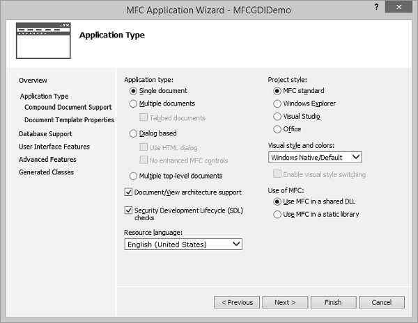
Step 2 − Once the project is created, go the Solution Explorer and double click on the MFCGDIDemoView.cpp file under the Source Files folder.
Step 3 − Draw the line as shown below in CMFCGDIDemoView::OnDraw() method.
void CMFCGDIDemoView::OnDraw(CDC* pDC) {
   pDC->MoveTo(95, 125);
   pDC->LineTo(230, 125);
   CMFCGDIDemoDoc* pDoc = GetDocument();
   ASSERT_VALID(pDoc);
   if (!pDoc)
      return;

   // TODO: add draw code for native data here
}
Step 4 − Run this application. You will see the following output.
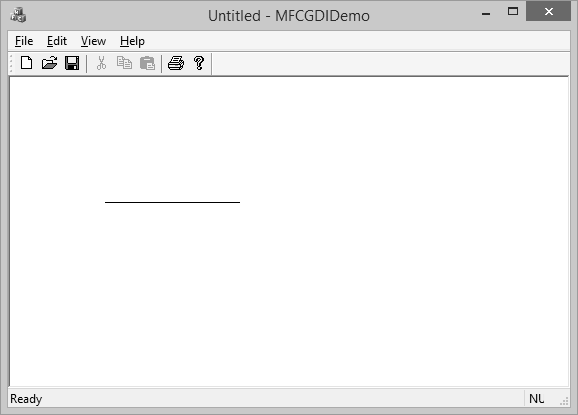
Step 5 − The CDC::MoveTo() method is used to set the starting position of a line.
When using LineTo(), the program starts from the MoveTo() point to the LineTo() end.
After LineTo() when you do not call MoveTo(), and call again LineTo() with other point value, the program will draw a line from the previous LineTo() to the new LineTo() point.
Step 6 − To draw different lines, you can use this property as shown in the following code.
void CMFCGDIDemoView::OnDraw(CDC* pDC) {
   pDC->MoveTo(95, 125);
   pDC->LineTo(230, 125);
   pDC->LineTo(230, 225);
   pDC->LineTo(95, 325);
   CMFCGDIDemoDoc* pDoc = GetDocument();
   ASSERT_VALID(pDoc);
   if (!pDoc)
      return;

   // TODO: add draw code for native data here
}
Step 7 − Run this application. You will see the following output.
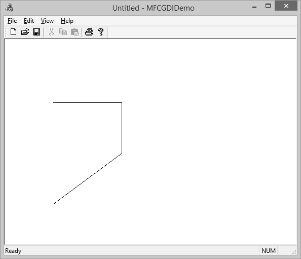
Polylines
A polyline is a series of connected lines. The lines are stored in an array of POINT or CPoint values. To draw a polyline, you use the CDC::Polyline() method. To draw a polyline, at least two points are required. If you define more than two points, each line after the first would be drawn from the previous point to the next point until all points have been included.
Step 1 − Let us look into a simple example.
void CMFCGDIDemoView::OnDraw(CDC* pDC) {
   CPoint Pt[7];
   Pt[0] = CPoint(20, 150);
   Pt[1] = CPoint(180, 150);
   Pt[2] = CPoint(180, 20);
   pDC−Polyline(Pt, 3);

   CMFCGDIDemoDoc* pDoc = GetDocument();
   ASSERT_VALID(pDoc);
   if (!pDoc)
      return;

   // TODO: add draw code for native data here
}
Step 2 − When you run this application, you will see the following output.
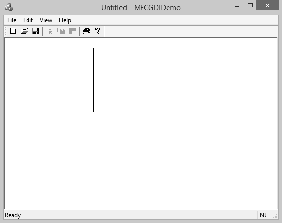
Rectangles
A rectangle is a geometric figure made of four sides that compose four right angles. Like the line, to draw a rectangle, you must define where it starts and where it ends. To draw a rectangle, you can use the CDC::Rectangle() method.
Step 1 − Let us look into a simple example.
void CMFCGDIDemoView::OnDraw(CDC* pDC) {
   pDC->Rectangle(15, 15, 250, 160);

   CMFCGDIDemoDoc* pDoc = GetDocument();
   ASSERT_VALID(pDoc);
   if (!pDoc)
      return;

   // TODO: add draw code for native data here
}
Step 2 − When you run this application, you will see the following output.
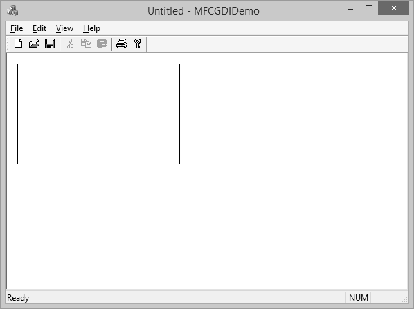
Squares
A square is a geometric figure made of four sides that compose four right angles, but each side must be equal in length.
Let us look into a simple example.
void CMFCGDIDemoView::OnDraw(CDC* pDC) {
   pDC->Rectangle(15, 15, 250, 250);

   CMFCGDIDemoDoc* pDoc = GetDocument();
   ASSERT_VALID(pDoc);
   if (!pDoc)
      return;

   // TODO: add draw code for native data here
}
When you run this application, you will see the following output.
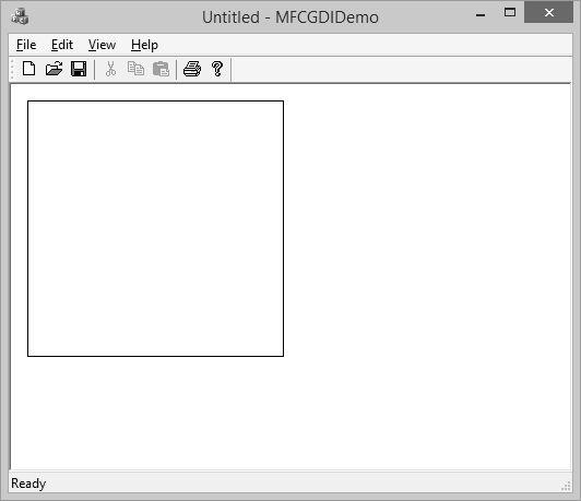
Pies
A pie is a fraction of an ellipse delimited by two lines that span from the center of the ellipse to one side each. To draw a pie, you can use the CDC::Pie() method as shown below −
BOOL Pie(int x1, int y1, int x2, int y2, int x3, int y3, int x4, int y4);
The (x1, y1) point determines the upper-left corner of the rectangle in which the ellipse that represents the pie fits. The (x2, y2) point is the bottom-right corner of the rectangle.
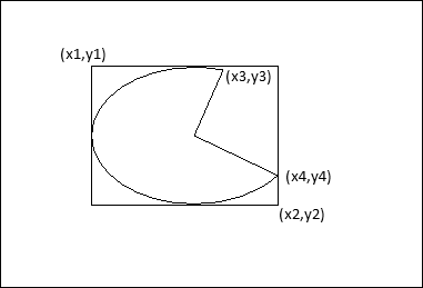
The (x3, y3) point specifies the starting corner of the pie in a default counterclockwise direction.
The (x4, y4) point species the end point of the pie.
Let us look into a simple example.
void CMFCGDIDemoView::OnDraw(CDC* pDC) {
   pDC->Pie(40, 20, 226, 144, 155, 32, 202, 115);

   CMFCGDIDemoDoc* pDoc = GetDocument();
   ASSERT_VALID(pDoc);
   if (!pDoc)
      return;

   // TODO: add draw code for native data here
}
Step 2 − When you run this application, you will see the following output.
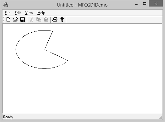
Arcs
An arc is a portion or segment of an ellipse, meaning an arc is a non-complete ellipse. To draw an arc, you can use the CDC::Arc() method.
BOOL Arc(int x1, int y1, int x2, int y2, int x3, int y3, int x4, int y4);
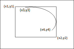
The CDC class is equipped with the SetArcDirection() method.
Here is the syntax −
int SetArcDirection(int nArcDirection)
| Sr.No. | Value & Orientation |
|---|---|
| 1 | AD_CLOCKWISE The figure is drawn clockwise |
| 2 | AD_COUNTERCLOCKWISE The figure is drawn counterclockwise |
Step 1 − Let us look into a simple example.
void CMFCGDIDemoView::OnDraw(CDC* pDC) {
   pDC->SetArcDirection(AD_COUNTERCLOCKWISE);
   pDC->Arc(20, 20, 226, 144, 202, 115, 105, 32);

   CMFCGDIDemoDoc* pDoc = GetDocument();
   ASSERT_VALID(pDoc);
   if (!pDoc)
      return;

   // TODO: add draw code for native data here
}
Step 2 − When you run this application, you will see the following output.
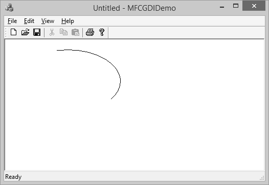
Chords
The arcs we have drawn so far are considered open figures because they are made of a line that has a beginning and an end (unlike a circle or a rectangle that do not). A chord is an arc whose two ends are connected by a straight line.
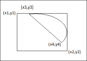
To draw a chord, you can use the CDC::Chord() method.
BOOL Chord(int x1, int y1, int x2, int y2, int x3, int y3, int x4, int y4);
Let us look into a simple example.
void CMFCGDIDemoView::OnDraw(CDC* pDC) {
   pDC->SetArcDirection(AD_CLOCKWISE);
   pDC->Chord(20, 20, 226, 144, 202, 115, 105, 32);

   CMFCGDIDemoDoc* pDoc = GetDocument();
   ASSERT_VALID(pDoc);
   if (!pDoc)
      return;

   // TODO: add draw code for native data here
}
When you run the above application, you will see the following output.
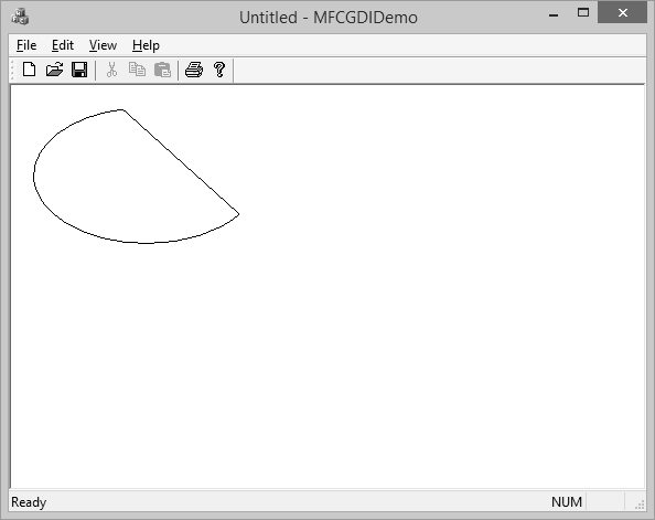
The arc direction in this example is set clockwise.
Colors
The color is one the most fundamental objects that enhances the aesthetic appearance of an object. The color is a non-spatial object that is added to an object to modify some of its visual aspects. The MFC library, combined with the Win32 API, provides various actions you can use to take advantage of the various aspects of colors.
The RGB macro behaves like a function and allows you to pass three numeric values separated by a comma. Each value must be between 0 and 255 as shown in the following code.
void CMFCGDIDemoView::OnDraw(CDC* pDC) {
   COLORREF color = RGB(239, 15, 225);
}
Let us look into a simple example.
void CMFCGDIDemoView::OnDraw(CDC* pDC) {
   COLORREF color = RGB(239, 15, 225);
   pDC->SetTextColor(color);
   pDC->TextOut(100, 80, L"MFC GDI Tutorial", 16);

   CMFCGDIDemoDoc* pDoc = GetDocument();
   ASSERT_VALID(pDoc);
   if (!pDoc)
      return;

   // TODO: add draw code for native data here
}
When you run this application, you will see the following output.
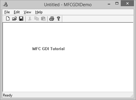
Fonts
CFont encapsulates a Windows graphics device interface (GDI) font and provides member functions for manipulating the font. To use a CFont object, construct a CFont object and attach a Windows font to it, and then use the object's member functions to manipulate the font.
Let us look into a simple example.
void CMFCGDIDemoView::OnDraw(CDC* pDC) {
   CFont font;
   font.CreatePointFont(920, L"Garamond");
   CFont *pFont = pDC->SelectObject(&font);
   COLORREF color = RGB(239, 15, 225);
   pDC->SetTextColor(color);
   pDC->TextOut(100, 80, L"MFC GDI Tutorial", 16);
   pDC->SelectObject(pFont);
   font.DeleteObject();

   CMFCGDIDemoDoc* pDoc = GetDocument();
   ASSERT_VALID(pDoc);
   if (!pDoc)
   return;

   // TODO: add draw code for native data here
}
When you run the above application, you will see the following output.
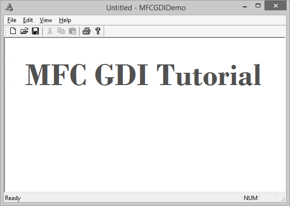
Pens
A pen is a tool used to draw lines and curves on a device context. In the graphics programming, a pen is also used to draw the borders of a geometric closed shape such as a rectangle or a polygon. Microsoft Windows considers two types of pens — cosmetic and geometric.
A pen is referred to as cosmetic when it can be used to draw only simple lines of a fixed width, less than or equal to 1 pixel. A pen is geometric when it can assume different widths and various ends. MFC provides a class CPen which encapsulates a Windows graphics device interface (GDI) pen.
Let us look into a simple example.
void CMFCGDIDemoView::OnDraw(CDC* pDC) {
   CPen pen;
   pen.CreatePen(PS_DASHDOTDOT, 1, RGB(160, 75, 90));
   pDC->SelectObject(&pen);
   pDC->Rectangle(25, 35, 250, 125);

   CMFCGDIDemoDoc* pDoc = GetDocument();
   ASSERT_VALID(pDoc);
   if (!pDoc)
      return;

   // TODO: add draw code for native data here
}
When you run the above application, you will see the following output.
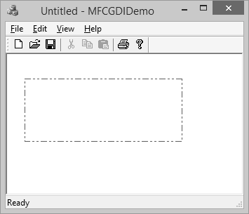
Brushes
A brush is a drawing tool used to fill out closed shaped or the interior of lines. A brush behaves like picking up a bucket of paint and pouring it somewhere. MFC provides a class CBrush which encapsulates a Windows graphics device interface (GDI) brush.
Let us look into a simple example.
void CMFCGDIDemoView::OnDraw(CDC* pDC) {
   CBrush brush(RGB(100, 150, 200));
   CBrush *pBrush = pDC->SelectObject(&brush);
   pDC->Rectangle(25, 35, 250, 125);
   pDC->SelectObject(pBrush);

   CMFCGDIDemoDoc* pDoc = GetDocument();
   ASSERT_VALID(pDoc);
   if (!pDoc)
      return;

   // TODO: add draw code for native data here
}
When you run this application, you will see the following output.
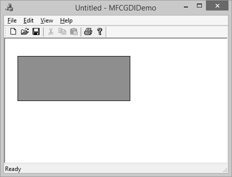
MFC - Libraries
A library is a group of functions, classes, or other resources that can be made available to programs that need already implemented entities without the need to know how these functions, classes, or resources were created or how they function. A library makes it easy for a programmer to use functions, classes, and resources etc. created by another person or company and trust that this external source is reliable and efficient. Some unique features related to libraries are −
A library is created and functions like a normal regular program, using functions or other resources and communicating with other programs.
To implement its functionality, a library contains functions that other programs would need to complete their functionality.
At the same time, a library may use some functions that other programs would not need.
The program that uses the library, are also called the clients of the library.
There are two types of functions you will create or include in your libraries −
An internal function is one used only by the library itself and clients of the library will not need access to these functions.
External functions are those that can be accessed by the clients of the library.
There are two broad categories of libraries you will deal with in your programs −
- Static libraries
- Dynamic libraries
Static Library
A static library is a file that contains functions, classes, or resources that an external program can use to complement its functionality. To use a library, the programmer has to create a link to it. The project can be a console application, a Win32 or an MFC application. The library file has the lib extension.
Step 1 − Let us look into a simple example of static library by creating a new Win32 Project.
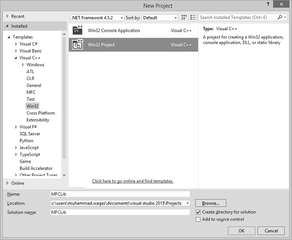
Step 2 − On Application Wizard dialog box, choose the Static Library option.
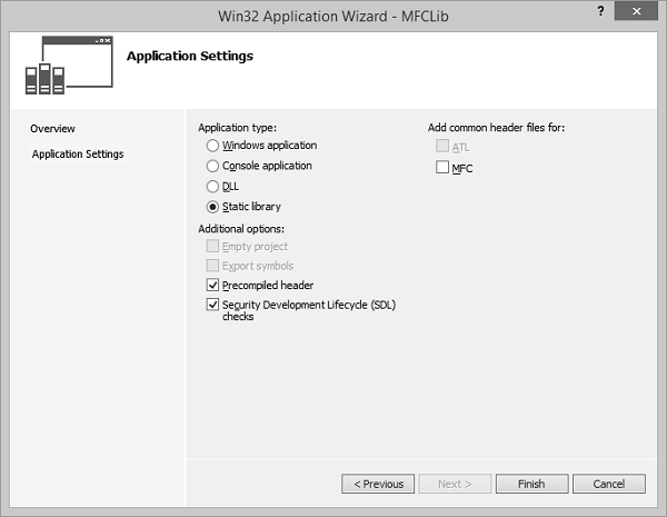
Step 3 − Click Finish to continue.
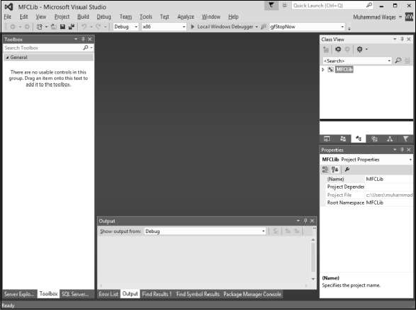
Step 4 − Right-click on the project in solution explorer and add a header file from Add → New Item…menu option.
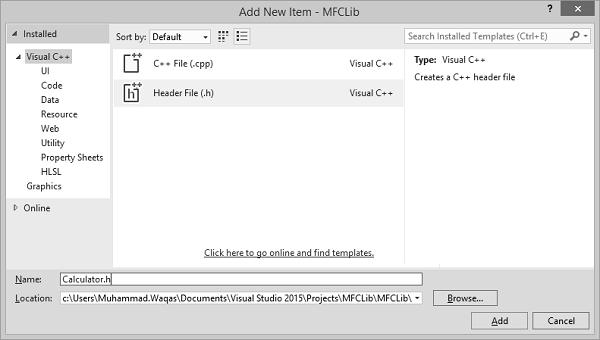
Step 5 − Enter Calculator.h in the Name field and click Add.
Add the following code in the header file −
#pragma once
#ifndef _CALCULATOR_H_
#define _CALCULATOR_H_
double Min(const double *Numbers, const int Count);
double Max(const double *Numbers, const int Count);
double Sum(const double *Numbers, const int Count);
double Average(const double *Numbers, const int Count);
long GreatestCommonDivisor(long Nbr1, long Nbr2);
#endif // _CALCULATOR_H_
Step 6 − Add a source (*.cpp) file in the project.
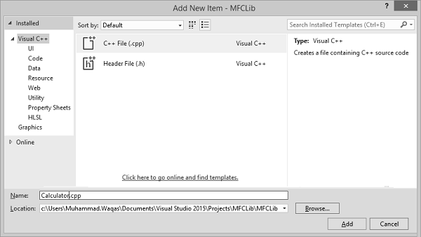
Step 7 − Enter Calculator.cpp in the Name field and click Add.
Step 8 − Add the following code in the *.cpp file −
#include "StdAfx.h"
#include "Calculator.h"
double Min(const double *Nbr, const int Total) {
   double Minimum = Nbr[0];
   for (int i = 0; i < Total; i++)
      if (Minimum > Nbr[i])
         Minimum = Nbr[i];
   return Minimum;
}
double Max(const double *Nbr, const int Total) {
   double Maximum = Nbr[0];
   for (int i = 0; i < Total; i++)
      if (Maximum < Nbr[i])
         Maximum = Nbr[i];
   return Maximum;
}
double Sum(const double *Nbr, const int Total) {
   double S = 0;
   for (int i = 0; i < Total; i++)
      S += Nbr[i];
   return S;
}
double Average(const double *Nbr, const int Total) {
   double avg, S = 0;
   for (int i = 0; i < Total; i++)
       S += Nbr[i];
   avg = S / Total;
   return avg;
}
long GreatestCommonDivisor(long Nbr1, long Nbr2) {
   while (true) {
      Nbr1 = Nbr1 % Nbr2;
      if (Nbr1 == 0)
         return Nbr2;
      Nbr2 = Nbr2 % Nbr1;
      if (Nbr2 == 0)
         return Nbr1;
   }
}
Step 9 − Build this library from the main menu, by clicking Build → Build MFCLib.
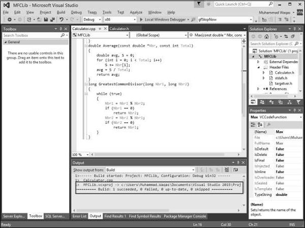
Step 10 − When library is built successfully, it will display the above message.
Step 11 − To use these functions from the library, let us add another MFC dialog application based from File → New → Project.
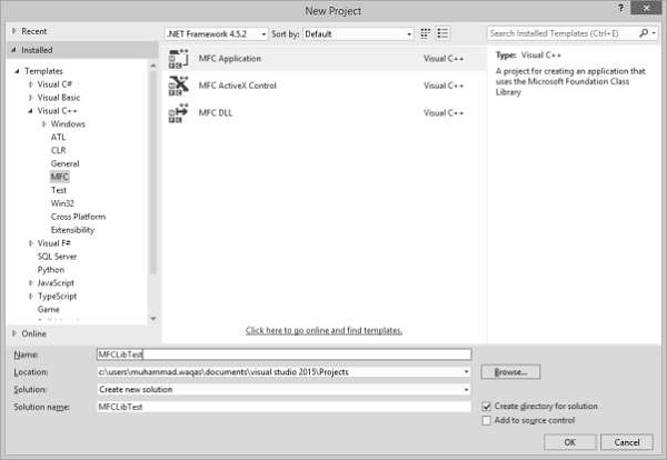
Step 12 − Go to the MFCLib\Debug folder and copy the header file and *.lib files to the MFCLibTest project as shown in the following snapshot.
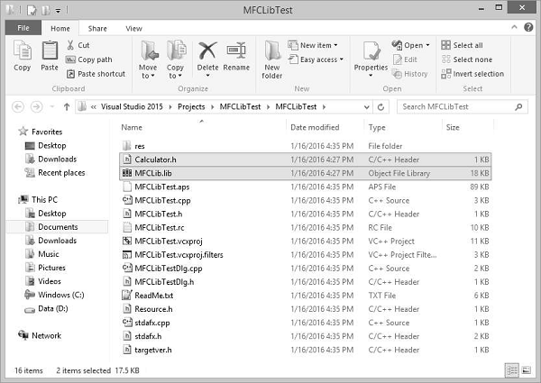
Step 13 − To add the library to the current project, on the main menu, click Project → Add Existing Item and select MFCLib.lib.
Step 14 − Design your dialog box as shown in the following snapshot.

Step 15 − Add value variable for both edit controls of value type double.

Step 16 − Add value variable for Static text control, which is at the end of the dialog box.

Step 17 − Add the event handler for Calculate button.
To add functionality from the library, we need to include the header file in CMFCLibTestDlg.cpp file.
#include "stdafx.h"
#include "MFCLibTest.h"
#include "MFCLibTestDlg.h"
#include "afxdialogex.h"
#include "Calculator.h"
Step 18 − Here is the implementation of button event handler.
void CMFCLibTestDlg::OnBnClickedButtonCal() {
   // TODO: Add your control notification handler code here
   UpdateData(TRUE);
   CString strTemp;
   double numbers[2];
   numbers[0] = m_Num1;
   numbers[1] = m_Num2;

   strTemp.Format(L"%.2f", Max(numbers,2));
   m_strText.Append(L"Max is:\t" + strTemp);

   strTemp.Format(L"%.2f", Min(numbers, 2));
   m_strText.Append(L"\nMin is:\t" + strTemp);

   strTemp.Format(L"%.2f", Sum(numbers, 2));
   m_strText.Append(L"\nSum is:\t" + strTemp);

   strTemp.Format(L"%.2f", Average(numbers, 2));
   m_strText.Append(L"\nAverage is:\t" + strTemp);

   strTemp.Format(L"%d", GreatestCommonDivisor(m_Num1, m_Num2));
   m_strText.Append(L"\nGDC is:\t" + strTemp);

   UpdateData(FALSE);
}
Step 19 − When the above code is compiled and executed, you will see the following output.
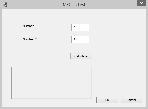
Step 20 − Enter two values in the edit field and click Calculate. You will now see the result after calculating from the library.
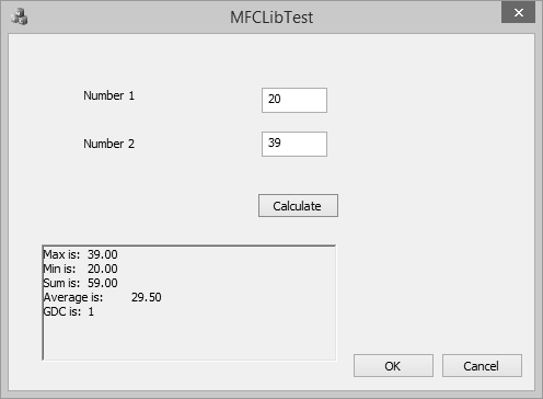
Dynamic Library
A Win32 DLL is a library that can be made available to programs that run on a Microsoft Windows computer. As a normal library, it is made of functions and/or other resources grouped in a file.
The DLL abbreviation stands for Dynamic Link Library. This means that, as opposed to a static library, a DLL allows the programmer to decide on when and how other applications will be linked to this type of library.
For example, a DLL allows difference applications to use its library as they see fit and as necessary. In fact, applications created on different programming environments can use functions or resources stored in one particular DLL. For this reason, an application dynamically links to the library.
Step 1 − Let us look into a simple example by creating a new Win32 Project.
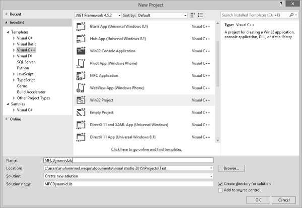
Step 2 − In the Application Type section, click the DLL radio button.
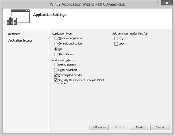
Step 3 − Click Finish to continue.
Step 4 − Add the following functions in MFCDynamicLib.cpp file and expose its definitions by using −
extern "C" _declspec(dllexport)
Step 5 − Use the _declspec(dllexport) modifier for each function that will be accessed outside the DLL.
// MFCDynamicLib.cpp : Defines the exported functions for the DLL application.//

#include "stdafx.h"

extern "C" _declspec(dllexport) double Min(const double *Numbers, const int Count);
extern "C" _declspec(dllexport) double Max(const double *Numbers, const int Count);
extern "C" _declspec(dllexport) double Sum(const double *Numbers, const int Count);
extern "C" _declspec(dllexport) double Average(const double *Numbers, const int Count);
extern "C" _declspec(dllexport) long GreatestCommonDivisor(long Nbr1, long Nbr2);

double Min(const double *Nbr, const int Total) {
   double Minimum = Nbr[0];
   for (int i = 0; i < Total; i++)
      if (Minimum > Nbr[i])
         Minimum = Nbr[i];
   return Minimum;
}
double Max(const double *Nbr, const int Total) {
   double Maximum = Nbr[0];
   for (int i = 0; i < Total; i++)
      if (Maximum < Nbr[i])
         Maximum = Nbr[i];
   return Maximum;
}
double Sum(const double *Nbr, const int Total) {
   double S = 0;
   for (int i = 0; i < Total; i++)
      S += Nbr[i];
   return S;
}
double Average(const double *Nbr, const int Total){
   double avg, S = 0;
   for (int i = 0; i < Total; i++)
      S += Nbr[i];
   avg = S / Total;
   return avg;
}
long GreatestCommonDivisor(long Nbr1, long Nbr2) {
   while (true) {
      Nbr1 = Nbr1 % Nbr2;
      if (Nbr1 == 0)
         return Nbr2;
      Nbr2 = Nbr2 % Nbr1;
      if (Nbr2 == 0)
         return Nbr1;
   }
}
Step 6 − To create the DLL, on the main menu, click Build > Build MFCDynamicLib from the main menu.
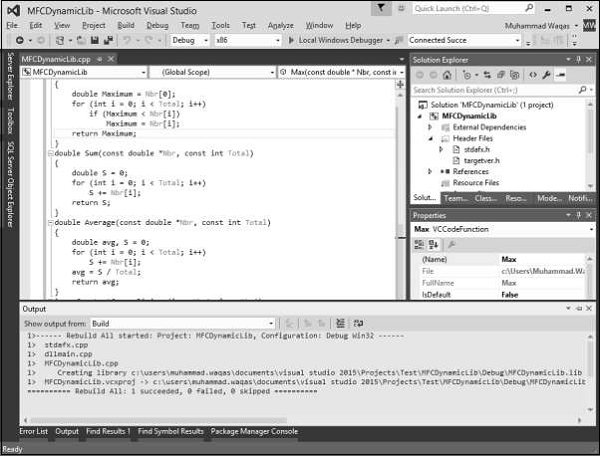
Step 7 − Once the DLL is successfully created, you will see amessage display in output window.
Step 8 − Open Windows Explorer and then the Debug folder of the current project.
Step 9 − Notice that a file with dll extension and another file with lib extension has been created.
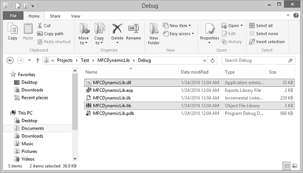
Step 10 − To test this file with dll extension, we need to create a new MFC dialog based application from File → New → Project.

Step 11 − Go to the MFCDynamicLib\Debug folder and copy the *.dll and *.lib files to the MFCLibTest project as shown in the following snapshot.
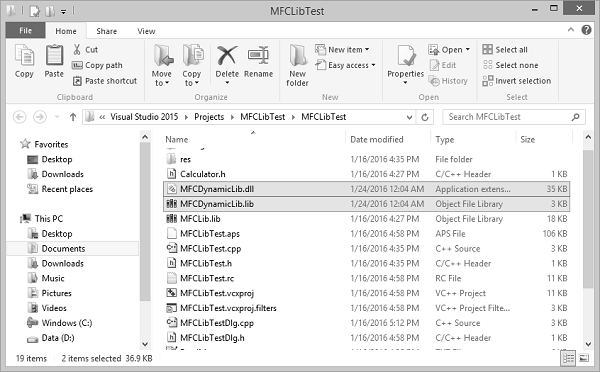
Step 12 − To add the DLL to the current project, on the main menu, click Project → Add Existing Item and then, select MFCDynamicLib.lib file.
Step 13 − Design your dialog box as shown in the following snapshot.
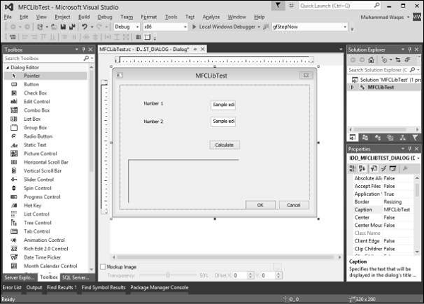
Step 14 − Add value variable for both edit controls of value type double.

Step 15 − Add value variable for Static text control, which is at the end of the dialog box.

Step 16 − Add the event handler for Calculate button.
Step 17 − In the project that is using the DLL, each function that will be accessed must be declared using the _declspec(dllimport) modifier.
Step 18 − Add the following function declaration in MFCLibTestDlg.cpp file.
extern "C" _declspec(dllimport) double Min(const double *Numbers, const int Count);
extern "C" _declspec(dllimport) double Max(const double *Numbers, const int Count);
extern "C" _declspec(dllimport) double Sum(const double *Numbers, const int Count);
extern "C" _declspec(dllimport) double Average(const double *Numbers, const int Count);
extern "C" _declspec(dllimport) long GreatestCommonDivisor(long Nbr1, long Nbr2);
Step 19 − Here is the implementation of button event handler.
void CMFCLibTestDlg::OnBnClickedButtonCal() {

   // TODO: Add your control notification handler code here
   UpdateData(TRUE);

   CString strTemp;
   double numbers[2];
   numbers[0] = m_Num1;
   numbers[1] = m_Num2;

   strTemp.Format(L"%.2f", Max(numbers,2));
   m_strText.Append(L"Max is:\t" + strTemp);

   strTemp.Format(L"%.2f", Min(numbers, 2));
   m_strText.Append(L"\nMin is:\t" + strTemp);

   strTemp.Format(L"%.2f", Sum(numbers, 2));
   m_strText.Append(L"\nSum is:\t" + strTemp);

   strTemp.Format(L"%.2f", Average(numbers, 2));
   m_strText.Append(L"\nAverage is:\t" + strTemp);

   strTemp.Format(L"%d", GreatestCommonDivisor(m_Num1, m_Num2));
   m_strText.Append(L"\nGDC is:\t" + strTemp);

   UpdateData(FALSE);
}
Step 20 − When the above code is compiled and executed, you will see the following output.
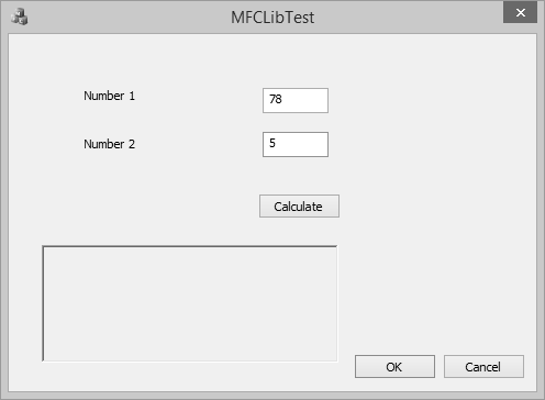
Step 21 − Enter two values in the edit field and click Calculate. You will now see the result after calculating from the DLL.


